
Spindle transmission component of CNC grinding (milling) groove machine tool

A technology for machine tool spindles and transmission components, applied to metal processing machinery parts, driving devices, metal processing equipment, etc., can solve the problems of easy wear of parts, easy wear of tracks, poor indexing accuracy, etc., to achieve convenient manufacturing and installation, and guarantee Machining accuracy and the effect of reducing the number of parts

Active Publication Date: 2010-07-28
丹阳市盛力机械有限公司
View PDF0 Cites 6 Cited by
  • Summary
  • Abstract
  • Description
  • Claims
  • Application Information

AI Technical Summary

Problems solved by technology

[0004] One method is to rely on the hydraulic motor to drive the spindle to rotate. The spindle is set with a lead with the same pitch as the workpiece, and a fixed slider is installed in the lead groove. When the spindle rotates, the spindle drives the workpiece to slide according to the pitch of the lead. Under the dominance of the block, it advances forward. When the main shaft retracts and rotates, the index plate that fixes the slider rotates to the required index angle under the action of friction, and then is positioned by the hydraulic mechanism to complete the action of the next process. The structure of the method is complicated, the parts are easy to wear, and the indexing accuracy is poor. The indexing plate and lead must be replaced according to the value of different workpieces, and it does not have the function of linear feeding;
[0005] Another method is to use a control motor to drive the main shaft to be responsible for the rotation and indexing of the main shaft. The main shaft is installed on the box, and the box is placed on a movable track. The lead screw cooperates to realize the overall linear movement of the box. Although this method has the above functions, its structure is complex, it takes up a lot of space, the track is easy to wear, and the product accuracy is not easy to guarantee.

Method used


Image

  • Spindle transmission component of CNC grinding (milling) groove machine tool
  • Spindle transmission component of CNC grinding (milling) groove machine tool

Examples


Embodiment Construction

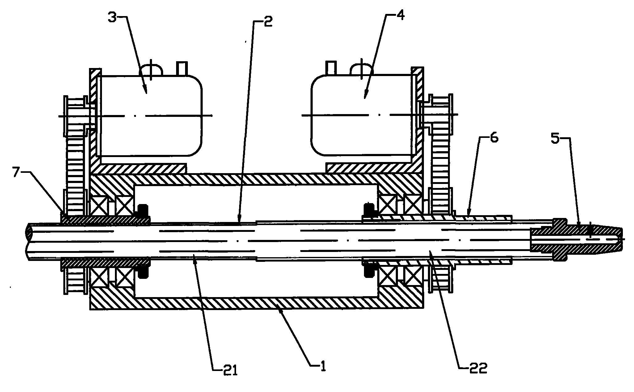
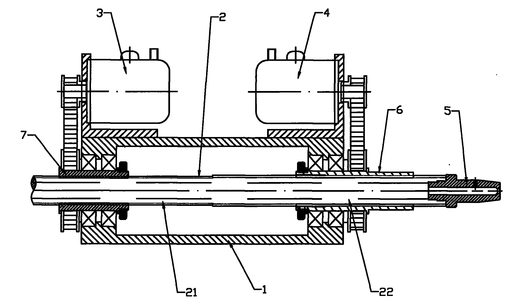
[0010] As shown in the figure, the spindle transmission components include a fixed box 1, a spindle 2, a linear feed CNC motor 3, and a rotary indexing CNC motor 4; the front end of the spindle 2 is equipped with a chuck 5 for clamping the workpiece; the spindle is divided into There are two coaxial front and rear sections; the front section of the main shaft is a spline shaft 21, and the spline shaft is covered with a spline sleeve 6, the main shaft can rotate with the spline sleeve and slide back and forth relative to the spline sleeve, and the spline sleeve 6 passes through The bearing is installed on the fixed box 1 and can be driven by the rotary indexing numerical control motor 4; It is installed on the fixed box 1 through bearings and driven by a linear feed numerical control motor 3 . The splined shaft 21 and the lead screw 22 that make up the main shaft 2 can be processed on one integral shaft, or can be processed separately by two shafts and then fixedly connected. ...


PUM


Abstract

The invention relates to a machine tool for processing machining tools such as drill bits, screw taps and milling cutters, in particular to a spindle transmission component of a CNC grinding (milling) groove machine tool. The component comprises a fixed tank, a spindle, a linear feed CNC motor and a rotary indexing CNC motor, wherein a collet used for clamping a work piece is arranged at the front end of the spindle; the spindle is divided into a front section and a rear section which are coaxial with each other; the front section of the spindle is a section of spline shaft outside which a spline sleeve is sleeved; the spindle can rotate along with the spindle sleeve and slide forward and backward relative to the spline sleeve; the spline sleeve is arranged on the fixed tank through a bearing and can be driven by the rotary indexing CNC motor; the rear section of the spindle is a section of screw rod matched with a screw rod pair; the spindle can be driven to move forward and backward by the screw rod pair; and the screw rod pair is arranged on the fixed tank through the bearing and is driven by the rotary indexing CNC motor. The spindle transmission component has the advantages of simple structure, small size, convenient manufacturing and installation and high processing accuracy.

Description

technical field [0001] The invention relates to a machine tool for machining drill bits, taps, milling cutters and other machining tools, in particular to a main shaft transmission part of a numerically controlled (milling) groove machine tool. Background technique [0002] Ordinary grinding (milling) groove machine tools used to process machining tools such as drill bits, taps, and milling cutters usually include: a bed, a grinding (milling) head part for processing tools, and a grinding (milling) head for controlling The lifting parts of the grinding (milling) head, the main shaft transmission parts used to clamp the workpiece and perform feeding and indexing, the numerical control system and other parts. Among them, the main shaft transmission part needs to drive the workpiece to be processed to perform linear feed and rotary indexing motion, so as to process straight or spiral grooves on drill bits, taps, milling cutters and other tools. [0003] There are two main type...

Claims


Application Information

Patent Timeline
IPC IPC(8): B23Q5/10B23Q5/32
Inventor 王仲林
Owner 丹阳市盛力机械有限公司
Learn More