Top cover for a metal drum and metal drum
A metal barrel and top cover technology, applied in the field of metal barrels, to achieve the effect of improving internal resistance, improving internal pressure resistance, and reducing deformation
- Summary
- Abstract
- Description
- Claims
- Application Information
AI Technical Summary
Problems solved by technology
Method used
Image

Examples
no. 1 approach
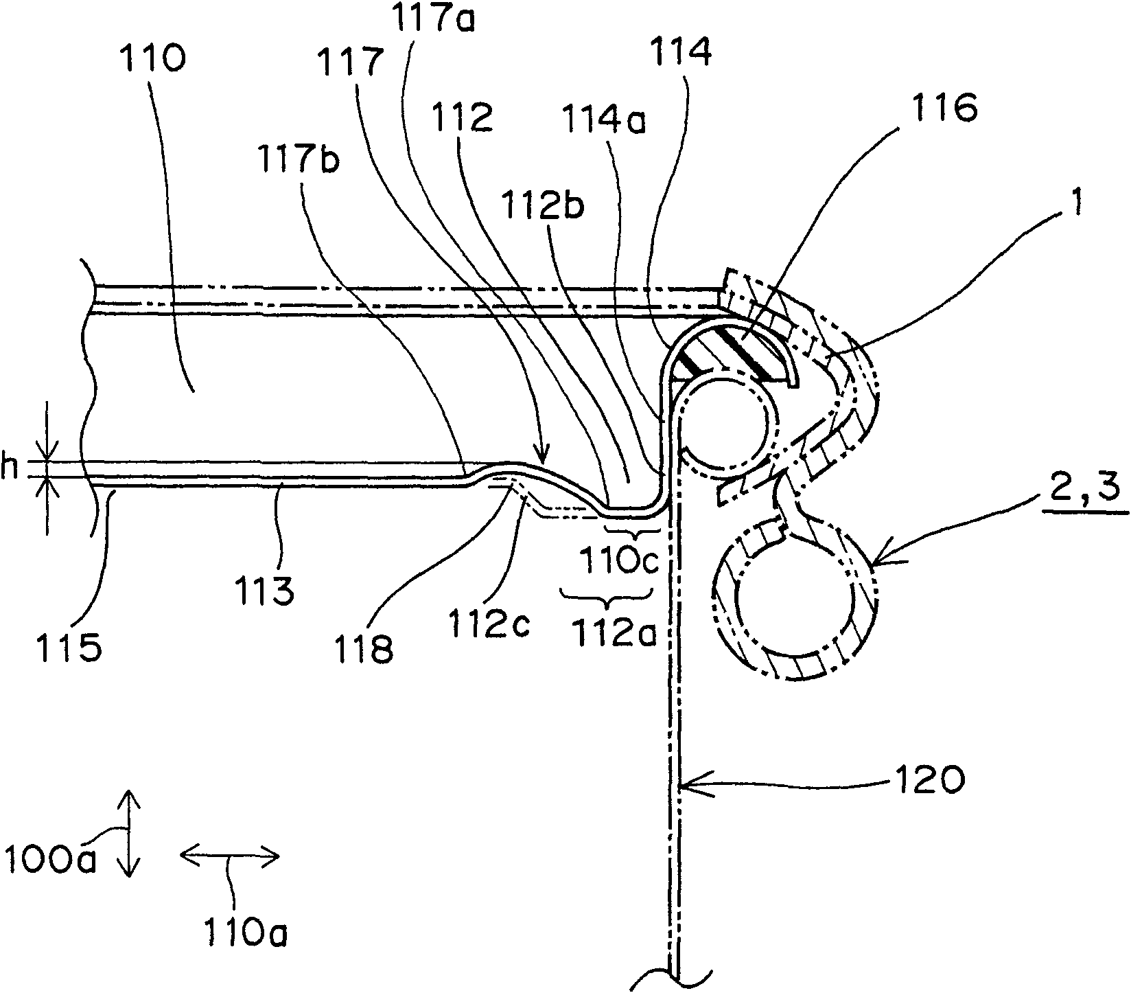
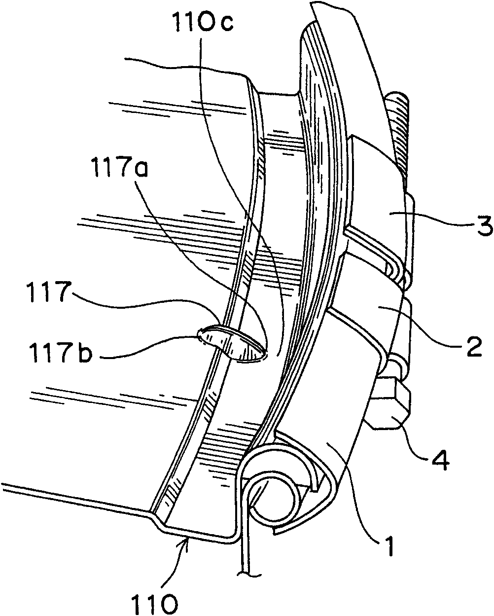
[0052] Such as Figure 4 As shown, the top cover 110 for metal drums in this embodiment is installed as a cover on the open-type metal drum 100 that can be disassembled with respect to the drum body 120. Fastened with barrel body 120 . Here, the open-ended metal bucket 100 is provided with a liner 116 ( figure 1 ), can be used as an open-ended metal barrel for internal pressure resistance. In the present embodiment, the steel metal barrel with an internal capacity of 200 liters is an example. It goes without saying that the capacity is not limited to 200 litres.
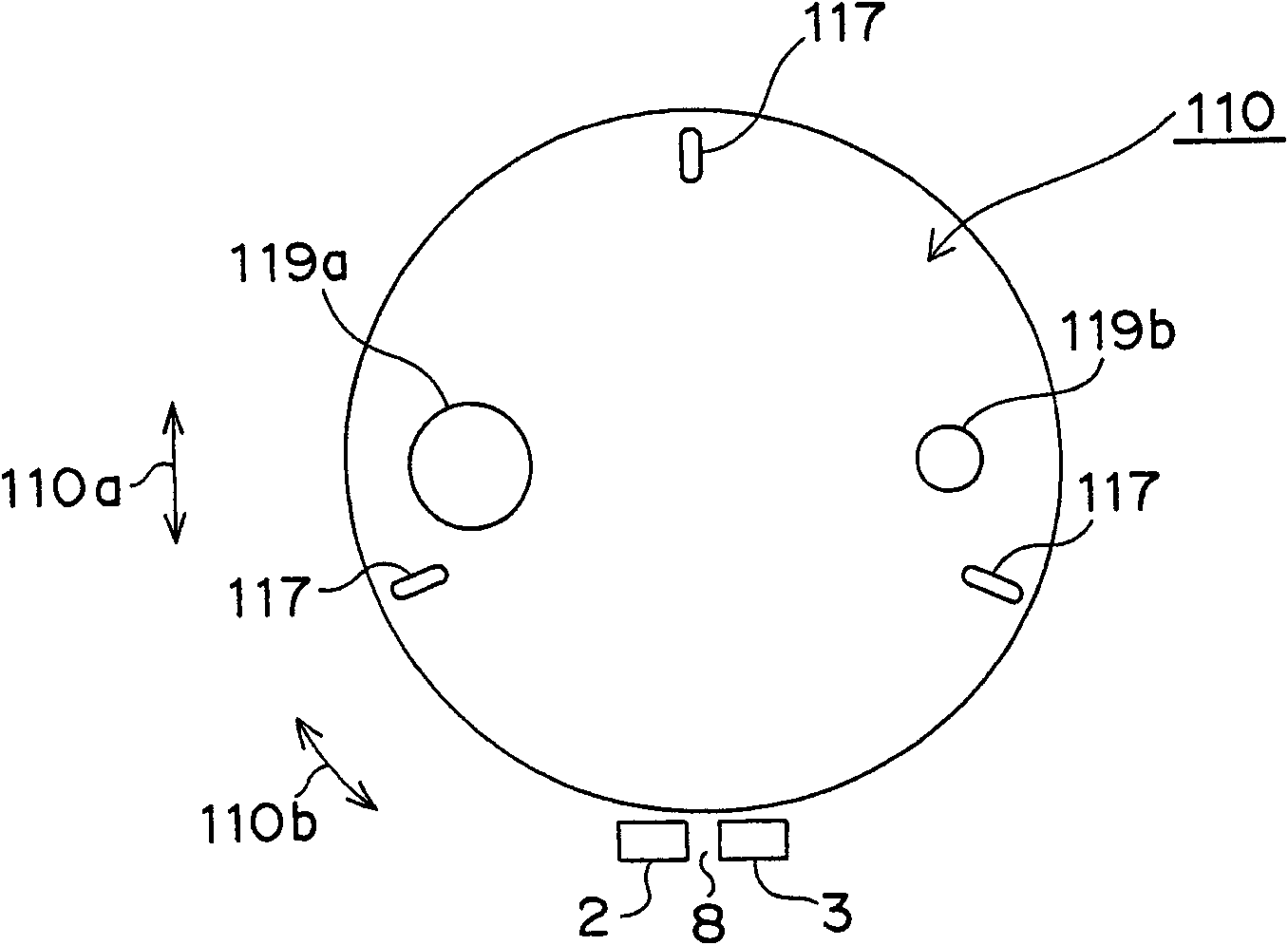
[0053] Additionally, if Figure 5 As shown, similarly to the conventional top cover 7 , a wrinkle-removing portion 111 is formed on the top cover 110 for metal drums. The top cover 110 for a metal bucket is formed by pressing a circular steel plate, and the wrinkle removing portion 111 is used to prevent wrinkles from being generated in the top cover 110 during the above-mentioned press work.
[0054] Such a wr...
no. 2 approach
[0078] In the first embodiment described above, the top cover 110 on which the wrinkle removing portion 111 is formed is taken as an example. On the other hand, there are also Image 6 and Figure 7 A so-called flat-topped top cover 110-1 without the crease removal portion 111 is shown. Like the deformation inducing portion 117 described above, the deformation inducing portion 117-1 that exists between the starting end 117a and the terminal end 117b along the diameter direction 110a of the top cover 110-1 can also be formed on this top cover 110-1, so as to be able to The same effects as in the first embodiment described above are obtained.
[0079] Here, the positions of the start end 117a and the end 117b of the deformation inducing part 117-1 may be the positions of the above-mentioned superordinate concept, or may be the limited positions described in the first embodiment. In addition, in Image 6 and Figure 7 The middle diagram shows the situation where the position...
no. 3 approach
[0081] In addition, the present applicant has improved the conventional fastening ring 10 for metal barrels, and developed Figure 8A and Figure 8B A modified fastening ring 200 is shown. In this improved fastening ring 200, the position where the locking members 221, 222 corresponding to the locking members 2, 3 are attached to the end of the belt-shaped member 210 corresponding to the belt-shaped member 1 has been studied, so that it is possible to prevent Generation of the discontinuity 8 described above. That is, if Figure 8A As shown, for the locking member 221, in order to form the area 214 overlapping with the belt-shaped member 210, the locking member 221 is separated from the one end surface 212a of the belt-shaped member 210 along the circumferential direction of the belt-shaped member 210 and the locking member 221 is fixed. on the strip member 210 . On the other hand, the locking member 222 protrudes from the other end surface 213 a of the belt-shaped member ...
PUM
 Abstract
Description
Claims
Application Information
 - R&D
- Intellectual Property
- Life Sciences
- Materials
- Tech Scout
- Unparalleled Data Quality
- Higher Quality Content
- 60% Fewer Hallucinations
Browse by: Latest US Patents, China's latest patents, Technical Efficacy Thesaurus, Application Domain, Technology Topic, Popular Technical Reports.
© 2025 PatSnap. All rights reserved.Legal|Privacy policy|Modern Slavery Act Transparency Statement|Sitemap|About US| Contact US: help@patsnap.com