Light guide module of optical fingerprint identification system

A fingerprint identification and light guide module technology, which is applied in the light guide, light guide, optics and other directions of the lighting system, can solve the problems of difficult assembly, high assembly cost, and uneconomic benefits

Active Publication Date: 2010-07-28
GINGY TECH
View PDF2 Cites 22 Cited by
  • Summary
  • Abstract
  • Description
  • Claims
  • Application Information

AI Technical Summary

Problems solved by technology

[0005] However, since the light guide plate 22 guides the incident light according to the principle of total reflection, during the assembly process, the incident angle between the light source 23 and the light guide plate 22...

Method used


Image

  • Light guide module of optical fingerprint identification system
  • Light guide module of optical fingerprint identification system
  • Light guide module of optical fingerprint identification system

Examples


Embodiment Construction

[0015] Below in conjunction with accompanying drawing and embodiment the present invention is described in detail:

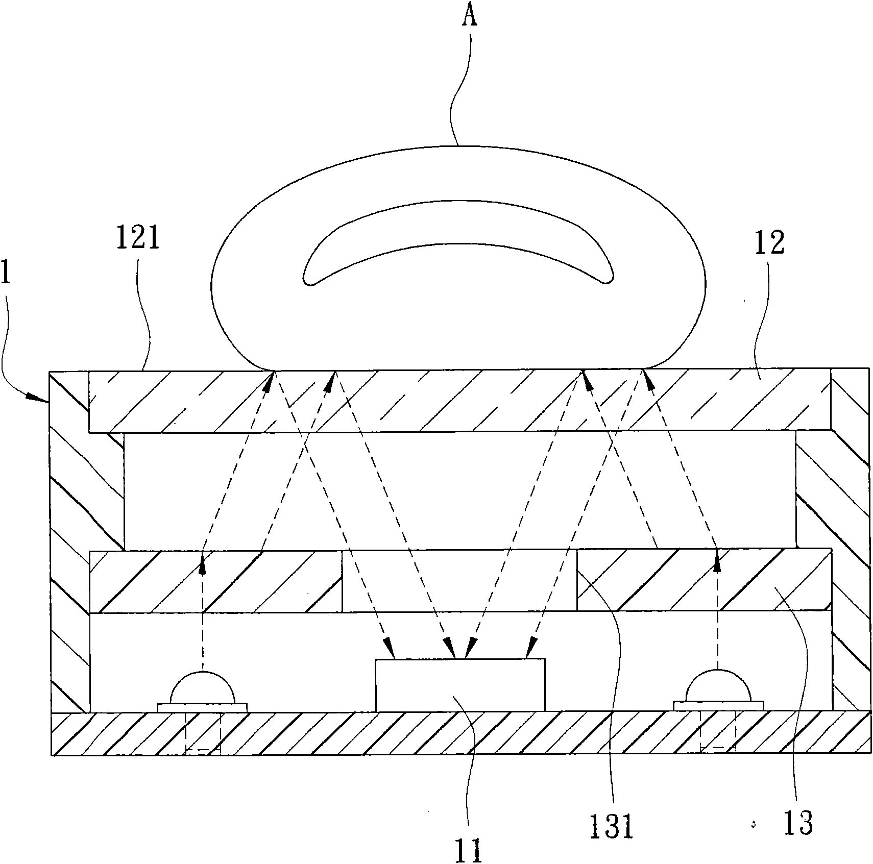
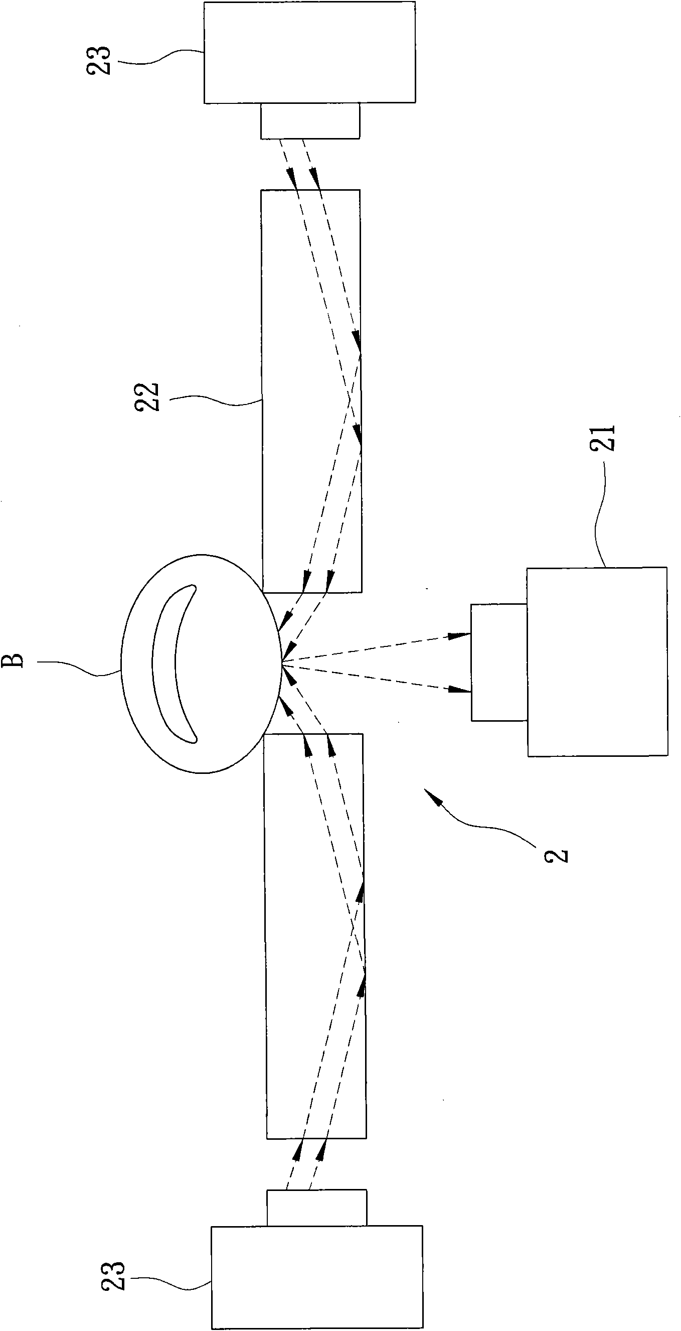
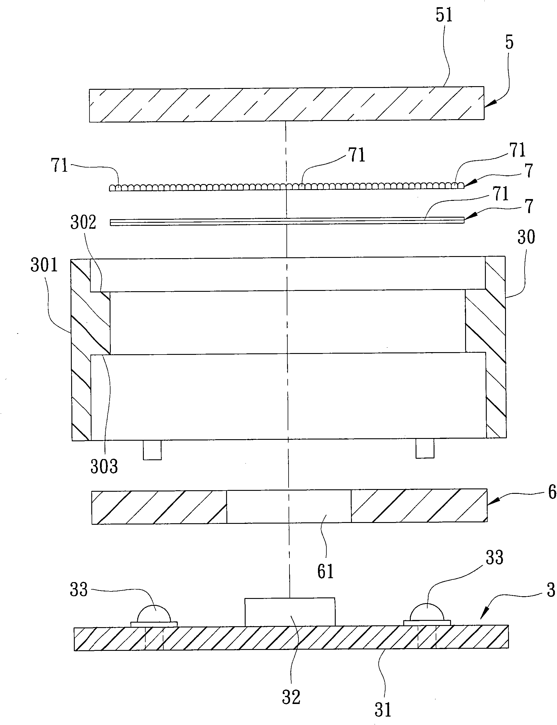
[0016] refer to image 3 ,and Figure 4 A first preferred embodiment of the light guide module of the optical fingerprint identification system of the present invention is installed in a fingerprint identification system 3 . The fingerprint recognition system 3 has a housing 30 , a circuit board 31 combined with the housing 30 , an imaging device 32 arranged on the circuit board 31 , and several light sources 33 for emitting light. The casing 30 has a ring wall 301 surrounding the imaging device 32 and the light source 33 , and a first step edge 302 and a second step edge 303 formed on an inner surface of the ring wall 301 . The aforementioned light sources 33 are respectively an LED lamp. The light guide module includes a pressing plate 5 , a light diffusing plate 6 , and two microstructure layers 7 .

[0017] In this preferred embodiment, the pressing plat...


PUM


Abstract

The invention discloses a light guide module of an optical fingerprint identification system. The light guide module guides the reflected light to an image sampling device and comprises a press plate for light transmittance and at least one light diffusion plate. The press plate is provided with a plate surface for a finger to press. The light diffusion plate is arranged between the image sampling device and the press plate and provided with an opening and a plurality of micro structures formed on a surface and guiding the incident lights to disperse on the surface of the press plate, wherein the opening is opposite to the press plate and the image sampling device and allows the reflected light to pass through. Therefore, the micro structure ensures that the incident lights are distributed on the press plate by adopting the micro structures, thereby increasing the light brightness focused on the finger, and further effectively improving the recognition rate.

Description

【Technical field】 [0001] The invention relates to a light guide module, in particular to a light guide module of an optical fingerprint recognition system using optical fingerprint identification. 【Background technique】 [0002] refer to figure 1 , an optical fingerprint identification system 1, including an image-taking device 11, and a pressing plate 12 and a light-diffusing plate 13 arranged above the image-taking device 11 in sequence from top to bottom. The pressing plate 12 has a plate surface 121 for the finger A to press. The light diffusing plate 13 guides the incident light to form a surface light source projecting towards the pressing plate 12 and has a through hole 131 through which the reflected light passes. When the surface light source is projected onto the finger A by the light diffusion plate 13, it will be reflected to the imaging device 11 below. Since the crests of the fingerprint reflect light and the troughs absorb light, the reflected light will for...

Claims


Application Information

Patent Timeline
IPC IPC(8): G06K9/00G02B6/00G02B5/02F21V8/00
Inventor 巫仁杰
Owner GINGY TECH
Why Eureka
Try Eureka