Sterilizing money counter structure

A technology of banknote counting machine and germicidal lamp, applied in counting mechanism/objects, instruments, counting objects, etc., can solve the problems of banknote clipping and ultraviolet light leakage, difficulty in sterilization, banknote counting, and low work efficiency, so as to improve sterilization. Efficiency, increased sterilization time, and easy maintenance

Inactive Publication Date: 2010-07-28
顾栽延
View PDF10 Cites 7 Cited by
  • Summary
  • Abstract
  • Description
  • Claims
  • Application Information

AI Technical Summary

Problems solved by technology

) However, due to the addition of sterilizing lamps, the existing money counters are structurally difficult to meet the needs of sterilization and counting money, and there are problems such as unsmooth running of money, sometimes jamming, clamping money when shutting down, and ultraviolet light leakage.
[0005] Existing commonly used banknote counting machines use fans to blow off the dust on the banknotes walking on the banknote walking channel, and the dust is directly blown out of the machine, causing pollution to the surrounding environment
When the money counter clipping occurs, the existing money counting machine can only take out the folder money after the machine is disassembled because the fuselage is a whole. Because the parts of the money counter are installed together by screws, therefore, It is very complicated and cumbersome to disassemble, and the work efficiency is low

Method used


Image

  • Sterilizing money counter structure
  • Sterilizing money counter structure
  • Sterilizing money counter structure

Examples


Embodiment Construction

[0027] The present invention will be described in further detail below in conjunction with the accompanying drawings.

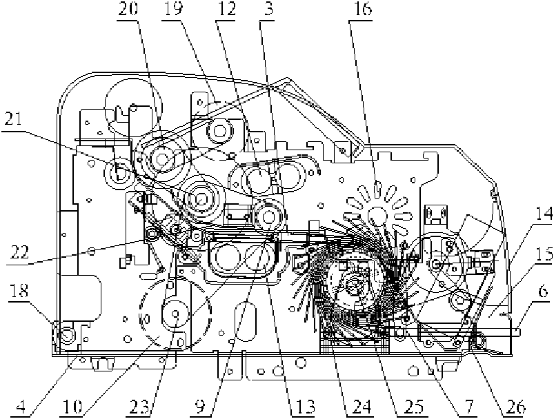
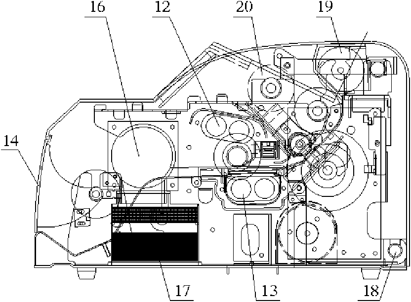
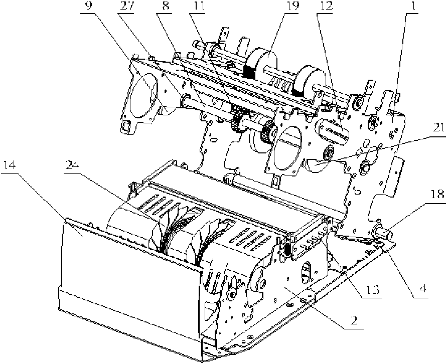
[0028] like Figure 1~5 As shown, the present invention includes a money-feeding mechanism, a money-moving mechanism and a money-receiving mechanism. The whole machine of the money counting machine is divided into two parts, an upper body 1 and a lower body 2, and a money-moving passage 3 is formed between the upper and lower bodies 1 and 2. The bottom of the lower body 2 is fixedly connected with the bottom plate 4, one end of the upper body 1 is hinged to the bottom plate 4 through the opening and closing fixed shaft 18, and the other end is a free end, which is engaged with the lower body 2; the upper body 1 can be opened along the hinged end or off. The upper body 1 is provided with a banknote feeding wheel 19, a twisting banknote wheel 20, a banknote passing wheel 21, a banknote passing plate 22, an upper germicidal lamp 12, an inertia wheel 9, a dust s...


PUM


Abstract

The invention relates to a money counter, in particular to a sterilizing money counter structure, which comprises a money feeding mechanism, a money passing mechanism and a money collecting mechanism, wherein a machine body of the money counter can be opened or closed along a money passing passage, the machine body of the money counter comprises an upper machine body and a lower machine body, the money passing passage is formed between the upper machine body and the lower machine body, one end of the upper machine body is hinged with a bottom plate, the other end of the upper machine body is a free end and is clamped and connected with the lower machine body, an inertia wheel shaft is arranged on the upper machine body, both ends of the inertia wheel shaft are respectively connected with side plates of both sides of the upper machine body through one-way bearings, a money outlet wheel and an inertia wheel which is driven through a main motor are arranged on the inertia wheel shaft, the upper end and the lower end of the money passing passage are respectively provided with an upper sterilizing lamp and a lower sterilizing lamp which are respectively arranged on the upper machine body and the lower machine body, the upper sterilizing lamp, the lower sterilizing lamp and the money outlet wheel form a sterilizing passage, and a turnable turning cover is arranged on the lower machine body. The invention can meet the requirements of three major functions of money counting, genuine and false discrimination and sterilization, and has the advantages of convenient maintenance and convenient use.

Description

technical field [0001] The invention relates to a money counting machine, in particular to a structure of a sterilization money counting machine. Background technique [0002] The appearance of the sterilizing banknote counter not only effectively solves the problem of sterilization and disinfection of currency in circulation, but also greatly improves the function of the banknote counter. The new generation of banknote counters with the three functions of counting, counterfeiting and sterilization are increasingly being used. The majority of users recognize and adopt it. [0003] A large number of germs and viruses are attached to the banknotes in circulation, which have been recognized by the world after being tested by the health and epidemic prevention department. It solves the problem of sterilization and disinfection of currency in circulation, improves the circulation environment of currency, and is beneficial to people's health. [0004] The Chinese patent (patent ...

Claims


Application Information

Patent Timeline
Patent Type & Authority Applications(China)
IPC IPC(8): G06M7/06A61L2/10A61L9/20
Inventor 顾栽延程虎赵睿
Owner 顾栽延
Why Eureka
Try Eureka