Partial PFC device and control method thereof

A control method and circuit technology, which are applied to some PFC devices for inverter air conditioner controllers and their control fields, can solve problems such as unsatisfactory effects, and achieve the effects of low device cost and reduced interference

Active Publication Date: 2010-07-28
MIDEA GRP CO LTD
View PDF3 Cites 20 Cited by
  • Summary
  • Abstract
  • Description
  • Claims
  • Application Information

AI Technical Summary

Problems solved by technology

This semi-active active power factor corrector and correction method can reduce the electromagnetic interfe

Method used


Image

  • Partial PFC device and control method thereof
  • Partial PFC device and control method thereof
  • Partial PFC device and control method thereof

Examples


no. 1 example

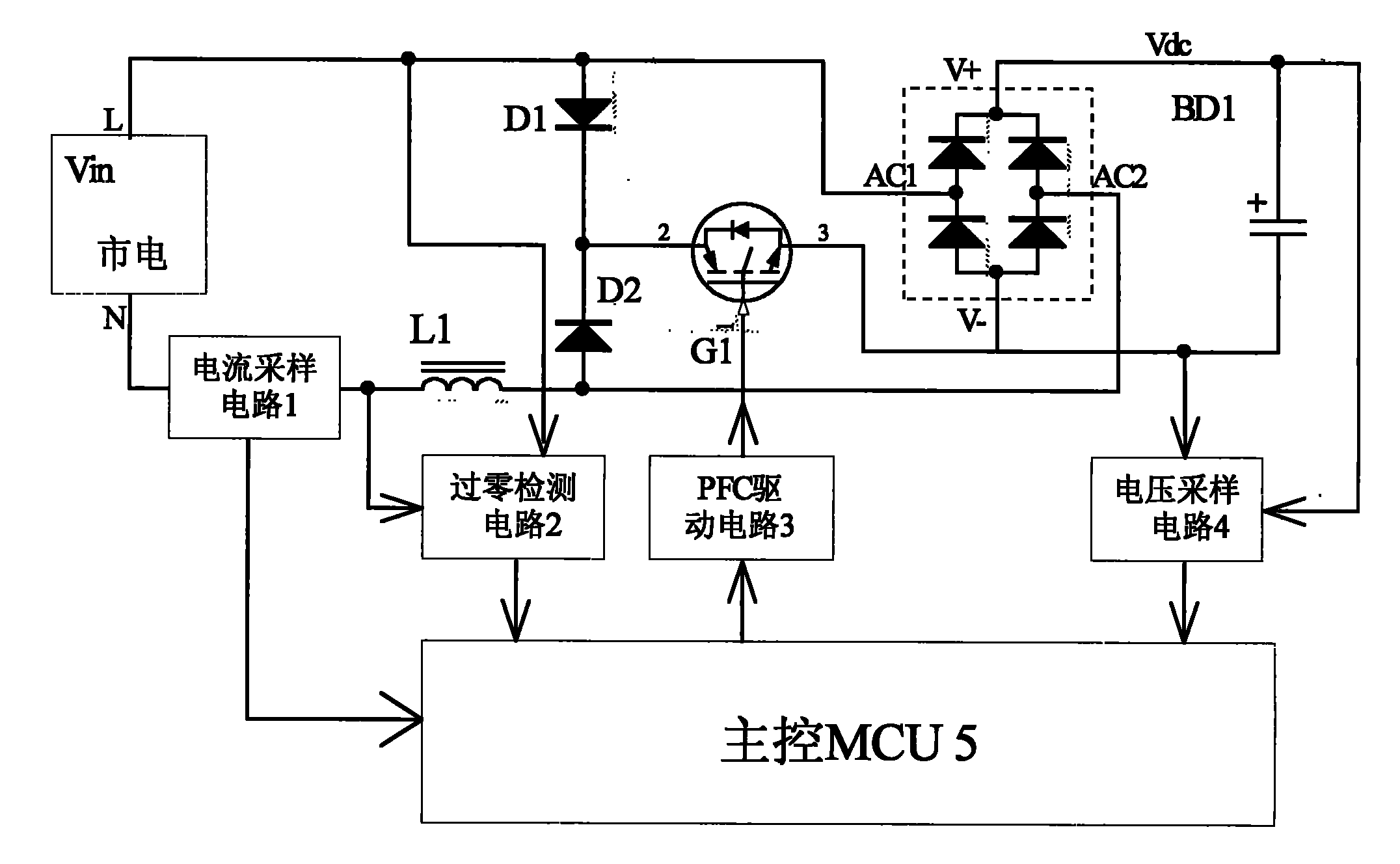
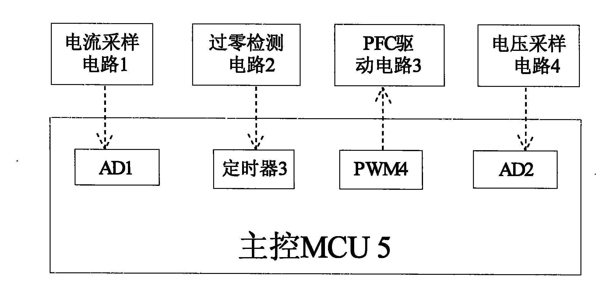
[0051] see Figure 1-Figure 4 , a partial PFC device, including a bridge rectifier BD1, mains power, a current sampling circuit 1, a zero-crossing detection circuit 2, an inductor L1, a diversion diode D1, a diversion diode D2, a power electronic switch G1, and a voltage sampling circuit 4 , PFC drive circuit 3 and main control MCU5. Among them, the live line L of the mains is connected to the anode of the diversion diode D1, the AC input terminal AC1 of the rectifier bridge BD1, and a sampling point of the zero-crossing detection circuit 2; the neutral line N of the mains is connected to one end of the current sampling circuit 1 The other end of the current sampling circuit 1 is connected to one end of the inductor L1 and the sampling point of the zero-crossing detection circuit 2; the other end of the inductor L1 is connected to the anode of the steering diode D2 and the AC2 end of the rectifier bridge stack BD1; power electronics The current inflow terminal 2 of the switch...

no. 2 example

[0078] see Figure 5 and Figure 2-Figure 4 Part of the PFC device includes rectifier bridge stack BD1, mains power, current sampling circuit 1, zero-crossing detection circuit 2, inductor L1, diversion diode D1, diversion diode D2, power electronic switch G1, voltage sampling circuit 4, PFC drive Circuit 3 and main control MCU5. Among them, the live line L of the mains is connected with the cathode of the diversion diode D1, the AC input terminal AC1 of the rectifier bridge BD1, and a sampling point of the zero-crossing detection circuit 2; the neutral line N of the mains is connected with one end of the current sampling circuit 1 ; The other end of the current sampling circuit 1 is connected to one end of the inductor L1 and the sampling point of the zero-crossing detection circuit 2; the other end of the inductor L1 is connected to the cathode of the steering diode D2 and the AC2 end of the rectifier bridge stack BD1; power electronics The current output terminal 3 of the...

no. 3 example

[0081] see Figure 6 and Figure 2-Figure 4 Part of the PFC device includes rectifier bridge stack BD1, mains power, current sampling circuit 1, zero-crossing detection circuit 2, inductor L1, diversion diode D1, diversion diode D2, power electronic switch G1, voltage sampling circuit 4, PFC drive Circuit 3 and main control MCU5. Wherein, the live line L of the mains is connected to one end of the inductor L1 and a sampling point of the zero-crossing detection circuit 2; the other end of the inductor L1 is connected to the cathode of the diversion diode D1 and the AC input terminal AC1 of the rectifier bridge BD1; The neutral line N of the mains is connected to one end of the current sampling circuit 1; the other end of the current sampling circuit 1 is connected to the sampling point of the zero-crossing detection circuit 2, the cathode of the steering diode D2, and the AC2 end of the rectifier bridge stack BD1; the power electronics The current inflow terminal 2 of the swi...


PUM


Abstract

The invention discloses a partial PFC device and control method thereof. The partial PFC device comprises a bridge rectifier BDI and utility power. The invention is characterized in that the device comprises a sampling circuit 1,a zero-crossing detection circuit 2, an inductor L1, a diversion diode D1, a diversion diode D2,a power electronic switch G1, voltage sampling circuit 4, a PFC drive circuit 3 and a master MCU5 in which the firing line L of the utility power is connected to the positive electrode of diversion diode, the AC input terminal AC1 of the bridge rectifier BDI and a sampling point of the zero-crossing detection circuit 2.The null line N is connected to one end of the current sampling circuit. The other end of the current sampling circuit 1 is connected to one end of the electronic sensor L1 and the sampling point of the zero-crossing detection circuit 2.The invention is simple and reasonable in structure and easy to operate. The invention can perform partial control of PFC, and effectively reduce the occurrences of EMC problems. The invention is low in cost yet high in power factor and able to enhance the output DC voltage.

Description

technical field [0001] The invention relates to a partial PFC device and a control method thereof, in particular to a partial PFC device and a control method thereof for an inverter air conditioner controller. Background technique [0002] At present, PFC is widely used in the field of inverter air conditioner control. [0003] The power factor correction effect of the passive PFC circuit is not good, the maximum can only reach about 0.9, and in the current environment of rising prices of basic raw materials, the cost is also high, and another defect is that the rectified DC voltage drops significantly when the current is high , affecting the latter stage, such as compressors and other loads cannot work at high operating frequencies. [0004] The full active PFC power factor correction effect is good, can reach more than 0.99, but because of the high cost, especially the high-speed hard switch chopping, the high-frequency interference is very serious, resulting in serious e...

Claims


Application Information

Patent Timeline
IPC IPC(8): H02M1/42
CPCY02B70/126Y02B70/10
Inventor 王斌
Owner MIDEA GRP CO LTD
Why Eureka
Try Eureka