
Ball end mill

A ball-nose end mill, spherical technology, applied in the direction of milling cutter, milling machine equipment, manufacturing tools, etc., can solve the problems of shortened tool life, faster feed speed, increased feed rate, etc., to improve the surface roughness of processing , speed up the feed rate, increase the effect of the amount of feed

Active Publication Date: 2012-01-11
UNION TOOL
View PDF1 Cites 0 Cited by
  • Summary
  • Abstract
  • Description
  • Claims
  • Application Information

AI Technical Summary

Problems solved by technology

[0004] However, in the existing ball nose end mills, the discharge performance of the chip flute is poor. If the feed rate is increased and the amount of cutting is increased, chips will accumulate especially at the front end of the tool, which will induce re-cutting of chips. The damage such as the defect of the spherical edge or the chatter caused by chip jamming make the machining accuracy worse
In addition, cutting resistance increases due to chip jamming, which causes chipping, tipping, etc., and shortens tool life.

Method used


Image

  • Ball end mill
  • Ball end mill
  • Ball end mill

Examples


Embodiment

[0037] Specific embodiments of the present invention will be described with reference to the drawings.

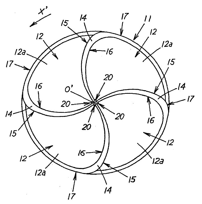
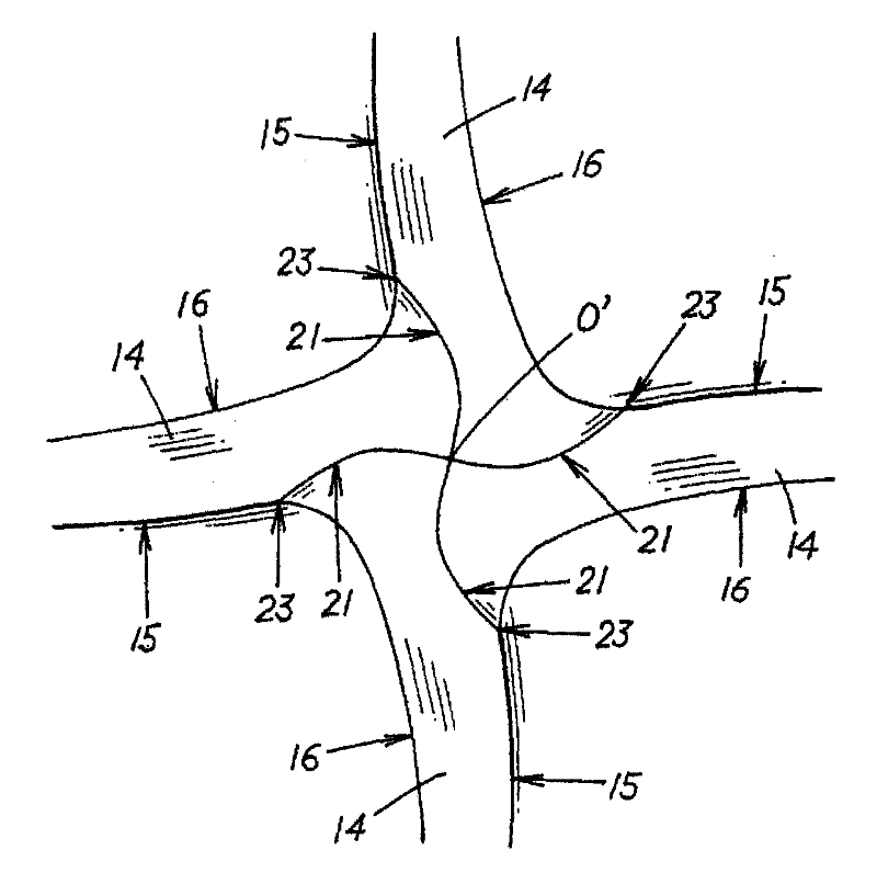
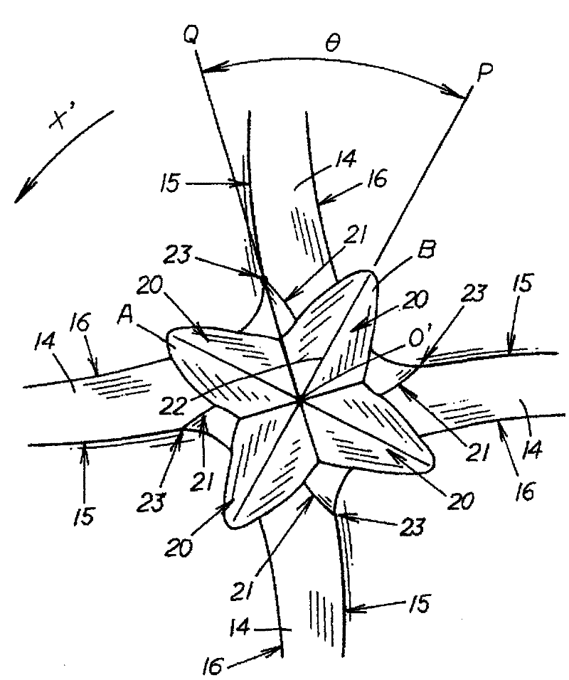
[0038] The present embodiment is a four-flute ball nose end mill as follows: four spiral chip flutes 12 are formed on the outer periphery of the tool body 11 from the tool front end toward the base end side, and on the rake face of the chip flutes 12 Spherical cutting edges 15 are respectively provided at the intersecting ridgelines intersecting with the secondary flank 14 of the tool main body 11, and at the intersecting ridgelines where the rake face of the flute 12 intersects with the outer peripheral surface of the tool main body 11 Forming the peripheral edge 17, this four-flute ball end mill has a shank connected to the tool mounting portion of the milling machine at the base end, and performs cutting such as three-dimensional machining on metals such as iron and steel materials mounted on the milling machine.

[0039] In addition, in the chip flute 12 is formed a sub...


PUM


Abstract

A ball end mill exhibiting extremely excellent practicality in which machining surface roughness can be improved while prolonging the lifetime. On the outer circumference of a tool body (11), a plurality of spiral chip discharge grooves (12) are formed from the distal end toward the proximal end of the tool, and a ball blade (15) is provided at the intersection ridge line of the face of the chip discharge groove (12) and the flank (14) at the distal end of the tool body (11). In such a ball end mill, two or more ball blades (15) are provided at the tip of the ball end mill, and one groove (20) having a substantially V-shaped or U-shaped cross-section and extending outward from the center (O') of rotation of the tool is provided between respective ball blades (15) at the distal end of the tool.

Description

technical field [0001] The present invention relates to ball nose end mills. Background technique [0002] For example, a general ball end mill as disclosed in Patent Document 1 is constituted by forming a plurality of helical chip flutes on the outer periphery of the tool body from the tool front end toward the base end side, and the rake flutes of the chip flutes Spherical cutting edges are provided at the intersecting ridges where the surface (すくいface) intersects with the sub-flank surface (tip escaping surface) of the tool body, and chips cut by the spherical cutting edge are discharged through the flutes. [0003] Patent Document 1: Japanese Patent Laid-Open No. 2005-224898 [0004] However, in the existing ball nose end mills, the discharge performance of the chip flute is poor. If the feed rate is increased and the amount of cutting is increased, chips will accumulate especially at the front end of the tool, which will induce re-cutting of chips. The damage such as ...

Claims


Application Information

Patent Timeline
Patent Type & Authority Patents(China)
IPC IPC(8): B23C5/10
CPCB23C2210/64B23C5/1009B23C2210/54
Inventor 古塩纯一高桥昭一
Owner UNION TOOL
Learn More