Rotary pump

A technology for motorized pumps and driven pumps, which is applied in the direction of machines/engines, pumps, pump devices, etc., which can solve the problems of technical extravagance, difficult vibration reduction measures, and insufficient use, so as to reduce air noise and solid noise emissions, reduce Accuracy requirements, effect of simple design

Active Publication Date: 2010-07-28
WILO SE
View PDF0 Cites 12 Cited by
  • Summary
  • Abstract
  • Description
  • Claims
  • Application Information

AI Technical Summary

Problems solved by technology

These measures have proven to be either insufficient or technically expensive, especially in the case

Method used


Image

  • Rotary pump
  • Rotary pump
  • Rotary pump

Examples


Embodiment Construction

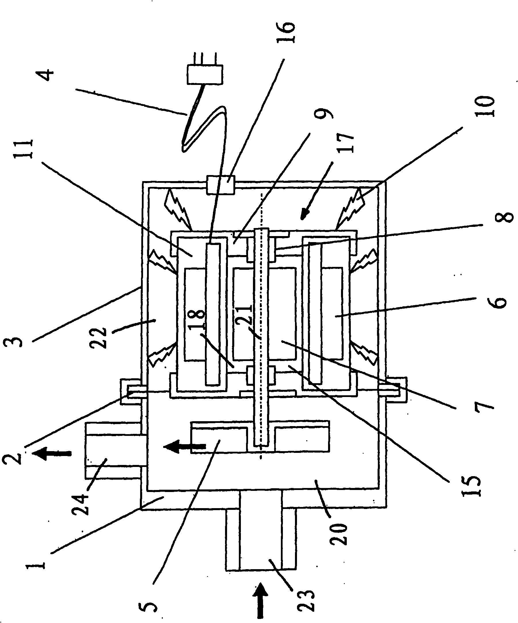
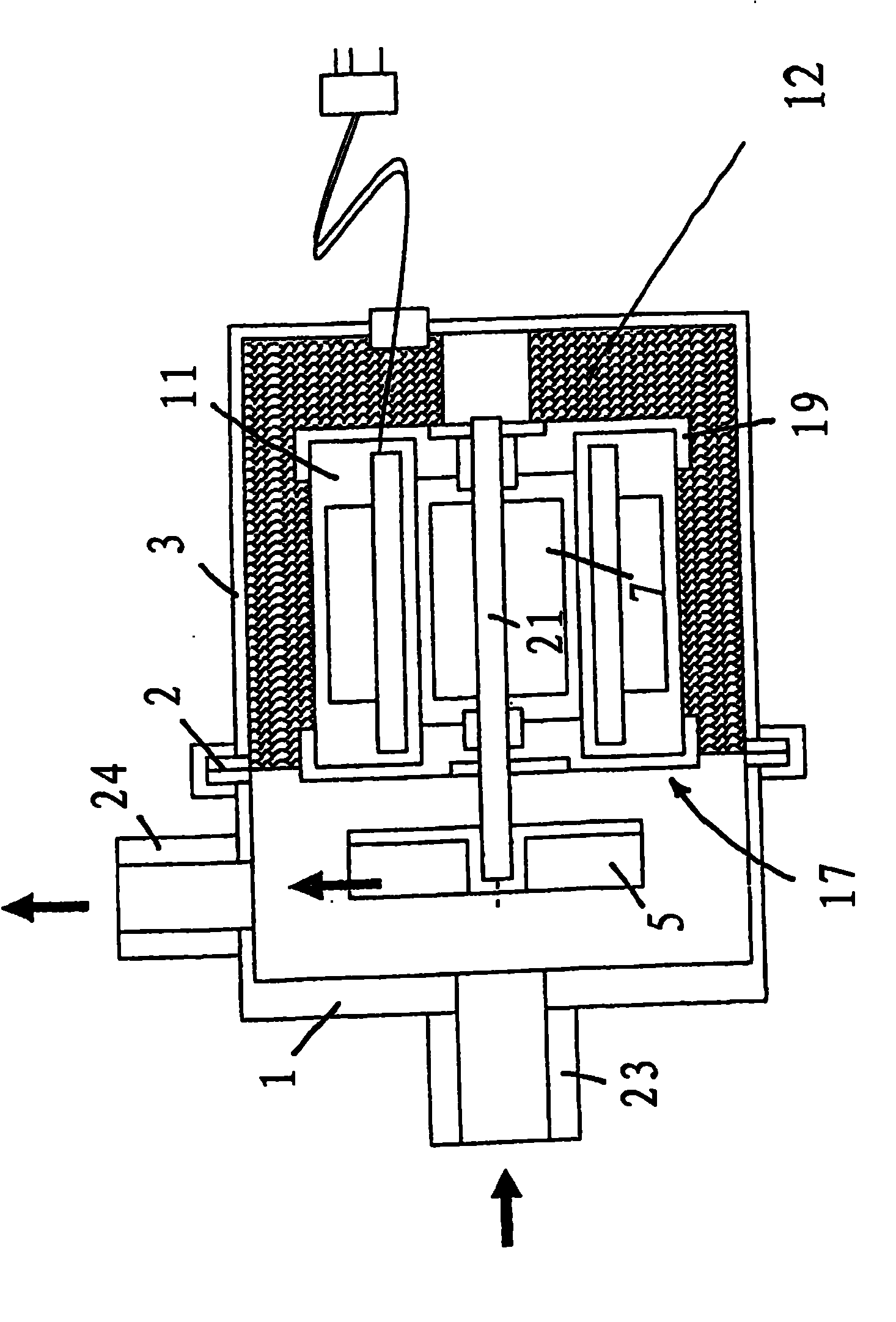
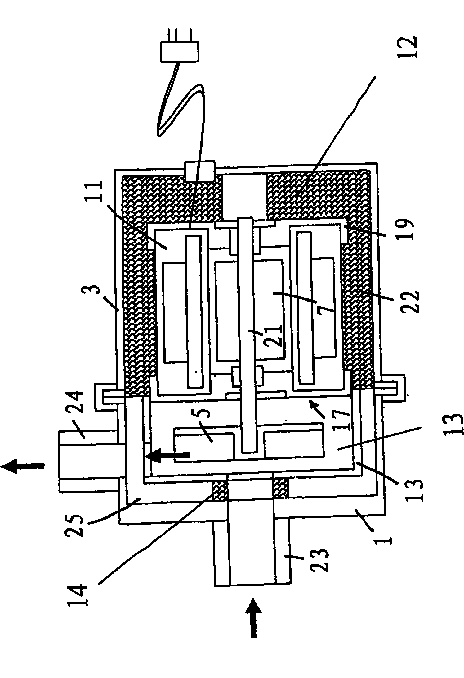
[0017] In each of the seven illustrated exemplary embodiments a rotary motor pump in the form of a wet rotor is involved. In this case, the motor stator 17 forms a cylindrical interior 18 through which the conveying fluid flows and in which the rotor 7 is mounted rotatably together with the motor shaft 21 . In this case, the stator 17 has windings 6 surrounding the space 18, these windings are sheathed by a thermosetting plastic or thermoplastic, so that the motor with its sheath 11 forms a unit from which the motor shaft 21 exits into the pump chamber , so that the impeller 5 of the pump is supported there.

[0018] On both sides of the jacket 11 , the motor stator 17 is surrounded by an inner motor housing 19 . However, this housing 19 can be omitted and can be replaced by the casing 11 . In all exemplary embodiments, the motor inner housing 19 forms part of the motor stator 17 .

[0019] The motor stator 17 is surrounded by the outer motor housing 3 at a distance such th...


PUM


Abstract

The invention relates to a rotary pump, particularly in a wet running design, the electric motor rotor (7) of which drives the pump impeller (5) via the shaft (21) thereof and is surrounded by the motor stator (17). The motor stator and the pump impeller are surrounded by the pump and motor housing (1, 3), forming an intermediate space (22, 25), wherein at least one vibration-damping element (10, 12, 28) is disposed in the intermediate space and supports the motor stator (17) in the pump and motor housing.

Description

technical field [0001] The invention relates to a rotary motor pump, in particular a rotary motor pump in the form of a wet rotor, the motor rotor of which drives the pump impeller with its shaft and is surrounded by the motor stator. Background technique [0002] In order to reduce the airborne and solid-borne noise emissions of rotary motor pumps, it is known to provide vibration damping measures on individual components, such as bearings or gap heads. It has been found that these measures are either insufficient or technically expensive, especially in the case of small pumps. It is difficult to implement the known vibration damping measures especially in small pumps. Contents of the invention [0003] The object of the present invention is to effectively reduce the airborne and solid-borne noise emissions in a rotary motor pump of the type mentioned above in a structurally simple manner, especially in pumps with small external dimensions. Furthermore, the object of th...

Claims


Application Information

Patent Timeline
IPC IPC(8): F04D13/06F04D29/66F04D29/42
CPCF04D29/669F04D29/426F04D13/0606
Inventor G·施特雷洛A·艾希曼
Owner WILO SE
Why Eureka
Try Eureka