Dynamic loading methods based on servo motor

A technology of dynamic loading and servo motors, which is applied in the direction of engine testing, machine/structural component testing, and measuring devices. It can solve the problems that the characteristics of DC motors cannot meet the needs of electric loading systems, and achieve good application prospects and operation. Easy, high-precision results

Inactive Publication Date: 2010-08-04
HARBIN INST OF TECH
View PDF4 Cites 38 Cited by
  • Summary
  • Abstract
  • Description
  • Claims
  • Application Information

AI Technical Summary

Problems solved by technology

[0003] The purpose of the present invention is to solve the problem that the characteristics of the DC motor cannot well meet the requirements of the electric loading system when the DC motor is used for electric loading, and provides a dynamic loading method based on the servo motor

Method used


Image

  • Dynamic loading methods based on servo motor
  • Dynamic loading methods based on servo motor
  • Dynamic loading methods based on servo motor

Examples


specific Embodiment approach 1

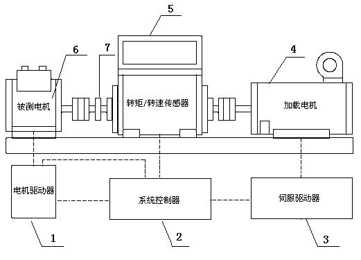
[0018] Specific implementation mode one: the following combination figure 1 To illustrate this embodiment, the device used in the method described in this embodiment includes a motor driver 1, a system controller 2, a servo driver 3, a loading motor 4, a torque / speed sensor 5, a motor under test 6 and an additional inertia disk 7, The loading motor 4, the torque / speed sensor 5 and the tested motor 6 are placed together on the test platform, the torque / speed sensor 5 is arranged between the loading motor 4 and the tested motor 6, the rotating shaft of the tested motor 6 and the torque The rotating shaft of the / speed sensor 5 is connected with a shaft coupling, the rotating shaft of the loading motor 4 is connected with the rotating shaft of the torque / speed sensor 5 with a coupling, and the rotating shaft of the loading motor 4 is provided with an additional inertia disk 7, The sum of the rotor inertia of the loading motor 4, the inertia of the torque / speed sensor 5, the inert...

specific Embodiment approach 2

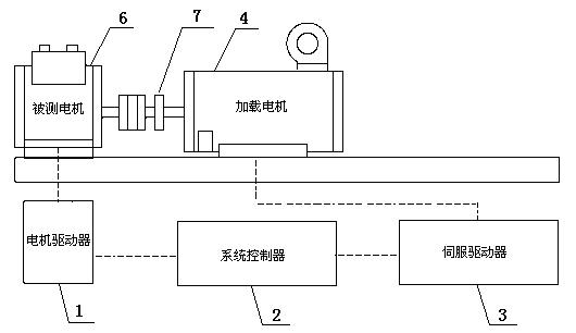
[0032]Specific implementation mode two: the following combination figure 2 Describe this embodiment, the device used in the method described in this embodiment includes a motor driver 1, a system controller 2, a servo driver 3, a loading motor 4, a motor under test 6 and an additional inertia disk 7, the load motor 4 and the motor under test 6 are placed together on the test platform, the rotating shaft of the tested motor 6 and the rotating shaft of the loading motor 5 are connected by a coupling, and the rotating shaft of the loading motor 4 is provided with an additional inertia disk 7, the rotor inertia of the loading motor 4, additional The sum of the inertia of the inertia disk 7 and the inertia of the shaft coupling is equal to the actual load inertia of the motor 6 under test,

[0033] The specific process of the dynamic loading method based on the servo motor is as follows:

[0034] First, the torque / speed sensor is used to calibrate the torque of the loading motor ...


PUM


Abstract

The invention relates to dynamic loading methods based on a servo motor, belonging to the field of motors and solving the problem that the properties of a direct-current motor can not satisfy the requirements of an electric loading system. The first method comprises the following steps of: transmitting a driving torque instruction value and an initial braking torque instruction value by utilizing a system controller according to the given loading spectrum to drive a measured motor to rotate; meanwhile, driving a loading motor to generate a braking torque for loading the measured motor; and then, feeding back the actual output torque value applied to the measured motor by the loading motor through adopting a torque/rotary speed sensor, and regulating the braking torque instruction value by utilizing the system controller according to a deviation so that the actual output torque value applied to the measured motor by the loading motor rapidly tracks the initial braking torque instruction value. The second method of the invention comprises the following steps of: calibrating the input and output torque relation curve of the loading motor by using the torque/rotary speed sensor, and then transmitting the driving torque instruction value and the braking torque instruction by using the system controller according to the given loading spectrum and the relation curve to load the measured motor.

Description

technical field [0001] The invention relates to a dynamic loading method based on a servo motor and belongs to the field of motors. Background technique [0002] As the national defense industry has greatly increased the control accuracy and maneuverability requirements of aircraft, higher requirements have been put forward for the dynamic frequency response and accuracy of the loading moment of the load simulator. With the rapid development of power electronics technology and computer control technology, servo motor technology has been significantly improved. In recent years, countries around the world have gradually replaced electro-hydraulic drive devices in many high-precision speed and position control occasions. There are two main reasons therein: one is that high-performance electric steering gears are being used more and more in many small unmanned aerial vehicles. The actuators of these steering gears are motors, so that the driving bandwidth and driving capacity ...

Claims


Application Information

Patent Timeline
Patent Type & Authority Applications(China)
IPC IPC(8): G01M15/02
Inventor 寇宝泉白崟儒刘奉海
Owner HARBIN INST OF TECH
Why Eureka
Try Eureka