Video display apparatus

A technology of image display device and display panel, which is applied in the direction of identification device, image enhancement, image analysis, etc., can solve the problems of not being recognized, and achieve the effect of suppressing whitening and saving power

Inactive Publication Date: 2010-08-04
HITACHI CONSUMER ELECTRONICS CORP
View PDF1 Cites 21 Cited by
  • Summary
  • Abstract
  • Description
  • Claims
  • Application Information

AI Technical Summary

Problems solved by technology

The liquid crystal display device described in Patent Document 1, such as Figure 12 As shown in (b), for an adjacent region of a certain width ( Figure 12 c) making the whitening ( Figure 12 Ab) not recognized

Method used


Image

  • Video display apparatus
  • Video display apparatus
  • Video display apparatus

Examples


Embodiment 1

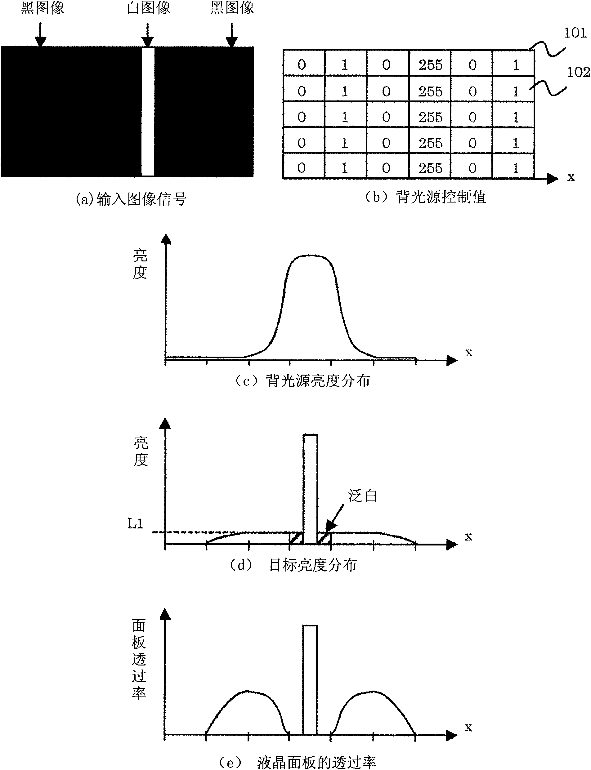
[0068] figure 1(a) input image signal, (b) backlight control value, (c) backlight luminance distribution, (d) target Brightness distribution, (e) Schematic diagram of the transmittance change of the liquid crystal panel. As an example, the above-mentioned input image signal is composed of a black image (for example, 8bit is 0) area and a white image (255) area, and when the display area (101) is divided into a plurality of areas, the independently controllable backlight area ( 102) Consists of 6 areas in the horizontal direction and 5 areas in the vertical direction, a total of 30 areas. In each area, one or a plurality of light sources, such as light emitting diodes, whose light intensity (brightness) can be individually controlled, are provided. By controlling the light source corresponding to each area, the brightness of the backlight in each area is controlled respectively. Hereinafter, each area is also referred to as a "backlight area".

[0069] The above-mentioned ...

Embodiment 2

[0112] In the second embodiment of the present invention, in order to keep the luminance distribution in the plane constant, the image signal set for the correction area is determined for each specific area, not based on the position information of the lighted area. In the second embodiment, the operation of the control filter (302), the method of determining the backlight control value (305) when the control signal 3 is ON, and the operation of the image signal correction unit (205) are different from those of the first embodiment.

[0113] Figure 9 It is a diagram classifying the display area (101) into three types of areas according to the second embodiment of the present invention.

[0114] The above-mentioned control filter receives the control signal 1 and the control signal 2 of each area from the histogram detection unit (301) of each area, and includes only the area where the control signal 1 is ON and the control signal 2 is ON in all areas. In the case of area I, ...

Embodiment 3

[0120] Figure 11 It is a circuit block diagram of the whole in the liquid crystal display device of the third embodiment of the present invention.

[0121] In the liquid crystal display device of this example, as shown in the figure, a moving image detection unit (1102) is added to the second embodiment. The moving image detection unit has a moving image detection unit represented by a motion vector for an input image signal, and sends its output to an image signal processing unit (1101), and the image signal processing unit uses the output change control method. However, as shown in the figure, the dynamic image detection unit does not have to be outside the image signal processing unit, and may be included in the image processing unit.

[0122] When a moving image is detected by the moving image detection means described above, the operation of the control filter (302) is different from that of the second embodiment. The above control filter changes according to the direc...


PUM


Abstract

For the purpose of obtaining a video signal by suppressing a black float while not consuming an excess electric power therein, not contributing to display of a backlight, a video display apparatus having a plural number of backlights for irradiating lights upon a display panel, comprises a histogram detector for conducting a histogram detection for each display region corresponding to that backlight from an input video signal of one (1) frame, a means for determining a control value of that plural number of backlights depending on a specific picture or video, which is detected by the histogram detector, and a video signal processor for controlling an amount of a controlled light the display panel of a display region, i.e., a put-out region, depending on the backlight control value, which is determined by the means for determining the control value of the backlight.

Description

technical field [0001] The present invention relates to an image display device that performs image display by modulating a backlight according to an image signal, and particularly relates to dividing an image display area into a plurality of areas and controlling the brightness of the backlight in an area corresponding to the image signal A lighting device, an image display device having the same, and an image display method. Background technique [0002] Display devices can be roughly classified into light-emitting display devices such as CRTs (Cathode Ray Tubes) and plasma display panels, and non-luminous display devices such as liquid crystal displays (also referred to as liquid crystal display devices, liquid crystal display panels). display device. [0003] Non-emissive display devices include a reflective light modulator that adjusts the amount of reflected light according to an image signal, and a device that uses a transmissive light modulator that adjusts the amou...

Claims


Application Information

Patent Timeline
Patent Type & Authority Applications(China)
IPC IPC(8): G09F9/35G09G3/36
CPCG09G3/3426G06T2207/20012G09G2360/16G09G5/00G06T5/008G06T5/40G09G2320/0646
Inventor 大木佑哉都留康隆田中和彦
Owner HITACHI CONSUMER ELECTRONICS CORP
Why Eureka
Try Eureka