

High frequency device, filter, duplexer, communication module, and communication apparatus
A technology of ladder filters and devices, which is applied in the fields of filters, high-frequency devices, communication modules and communication equipment, and duplexers. It can solve the problem of difficult to use IDT capacitors to balance filters, design IDT capacitor Q values without public IDT capacitors, etc. question
- Summary
- Abstract
- Description
- Claims
- Application Information
AI Technical Summary
Problems solved by technology
Method used
Image


Examples
Embodiment approach
[0043] [1. High-frequency device structure]
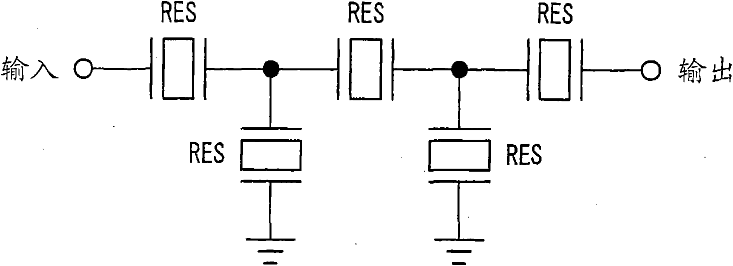
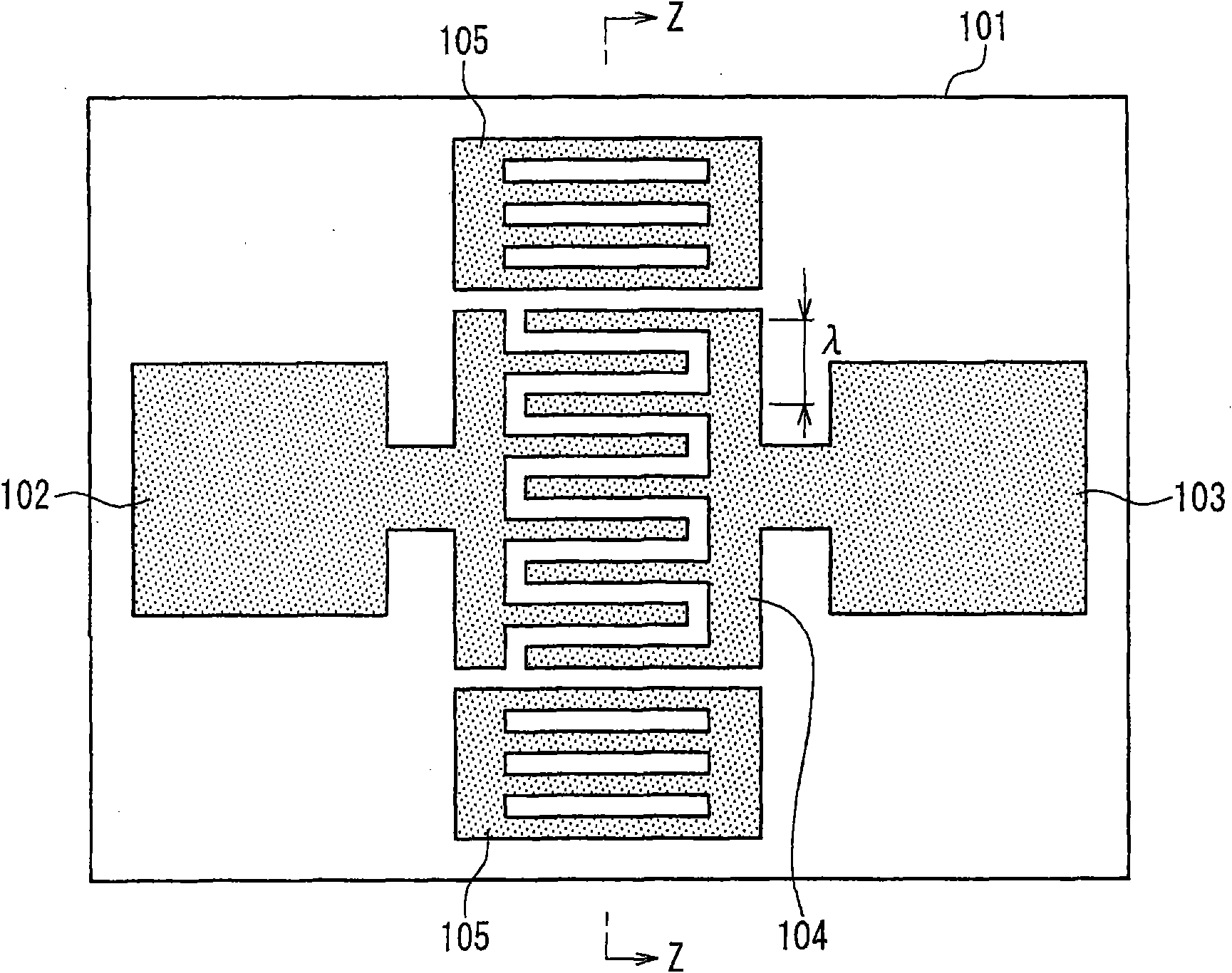
[0044] figure 1 is the circuit diagram of a ladder filter. In order to extract only high-frequency signals with desired frequencies, acoustic wave filters and duplexers are often used in mobile phone terminals. Specifically, often used as figure 1The shown acoustic resonator RES is connected as a ladder filter in a ladder configuration. Examples of resonators used as acoustic wave resonators included in ladder filters are Figure 2A ~ Figure 2C The surface acoustic wave resonator shown, such as Figure 3A ~ Figure 3C The Love wave resonator shown, such as Figure 4A ~ Figure 4C The boundary acoustic wave resonator shown in et al. Notice Figure 2A , 3A and 4A is the circuit diagram of the resonator. Figure 2B , 3B and 4B are plan views of the resonator. Figure 2C yes Figure 2B Sectional view of the Z-Z part of the middle. Figure 3C yes Figure 3B Sectional view of the Z-Z part of the middle. Figure 4C yes Fi...
no. 1 example
[0080] The following instructions Figure 14 An example of a balanced filter of this embodiment is shown.
[0081] Figure 19 yes Figure 14 Layout of the filter chip of the balanced filter shown. Such as Figure 19 As shown, the filter chip includes an input terminal 52 , output terminals 53 a and 53 b , a ladder filter 54 , a lattice filter 55 , and a ground terminal 57 formed on a monolithic piezoelectric substrate 51 . Ladder filter 54 includes series resonators 58a and 58b and parallel resonators 58c, 58d and 58e. The lattice filter 55 includes a series resonator 58h, a series resonator 58i, a parallel resonator 58k, and a parallel resonator 58j. The lumped constant balun includes a series inductor L1, a shunt inductor L2, and resonators 58f and 58g. The resonators 58f and 58g of the lumped constant balun function as capacitors, and can be realized by the IDT capacitor of the present embodiment. Here, will Figure 19 The gate pitch λ of the IDT capacitors (resonat...
no. 2 example
[0085] Figure 22 is a circuit diagram of the balanced duplexer in the second embodiment. Figure 22 The balanced duplexer shown is mainly composed of Figure 15 shown in the balanced duplexer to achieve, while the Figure 15 The matching circuit in Figure 16C The circuit shown is implemented.
[0086] Figure 23A A layout diagram of a transmit filter chip is shown as an example. Such as Figure 23A As shown, the transmit filter chip includes an input terminal 83a, a four-stage ladder filter 83b, an output terminal 83c and a ground terminal 83d.
[0087] Figure 23B A layout diagram of a receive filter chip is illustrated. Such as Figure 23B As shown, the receive filter chip includes a ladder filter 82b, a lattice filter 82c and a matching circuit resonator 82h on a monolithic piezoelectric substrate 81 . In addition, two IDT capacitors (resonators 82f and 82g) of this embodiment are formed on the same chip as capacitors of the lumped constant balun. Here, the gate ...
PUM
 Abstract
Description
Claims
Application Information