Endoscope device

A technology for endoscopes and snap-fit ​​parts, applied in the fields of endoscopes, telescopes, medical science, etc., can solve the problems of immobility, complicated structure and adjustment, and increased manufacturing costs, and achieve easy loading and unloading, simple structure, and easy manufacturing low cost effect

Inactive Publication Date: 2010-08-04
OLYMPUS CORP
View PDF3 Cites 14 Cited by
  • Summary
  • Abstract
  • Description
  • Claims
  • Application Information

AI Technical Summary

Problems solved by technology

[0012] However, in the first connection structure of Patent Document 1, when such a structure is applied to an endoscope, in order to make a set of (two) wires for bending the distal end of the endoscope opposite to each other, One wire can move in the front and rear direction, but the other wire cannot move backward from its position because the tooth part is in contact with the alignment part.
Therefore, it is impossible to apply such a continuous connection structure to an endoscope
[0013] In addition, in the second continuous connection structure, since it is necessary to provide a sensor for detecting the position of the wire at the front end side of the treatment instrument, and to move the wire one by one after connection to eliminate slack and detect the correct position of the wire, the structure and The adjustment is complicated and the manufacturing cost increases
In addition, in the third continuous connection structure, since there is no disclosure of a technique for keeping the tooth parts in a meshed state with each other, it is not clear whether this structure can be applied to an endoscope
[0014] In addition, in the structure of the endoscope described in Patent Document 2, since the position of the wire at the time of attachment and detachment is unknown, it is necessary to detect the position of the wire with an encoder, so the manufacturing cost of the bending pull mechanism on the detachment side increases. , and in addition to the increase in cost, the structure is also enlarged

Method used


Image

  • Endoscope device
  • Endoscope device
  • Endoscope device

Examples


Embodiment Construction

[0070] Hereinafter, embodiments of the present invention will be described in detail with reference to the drawings.

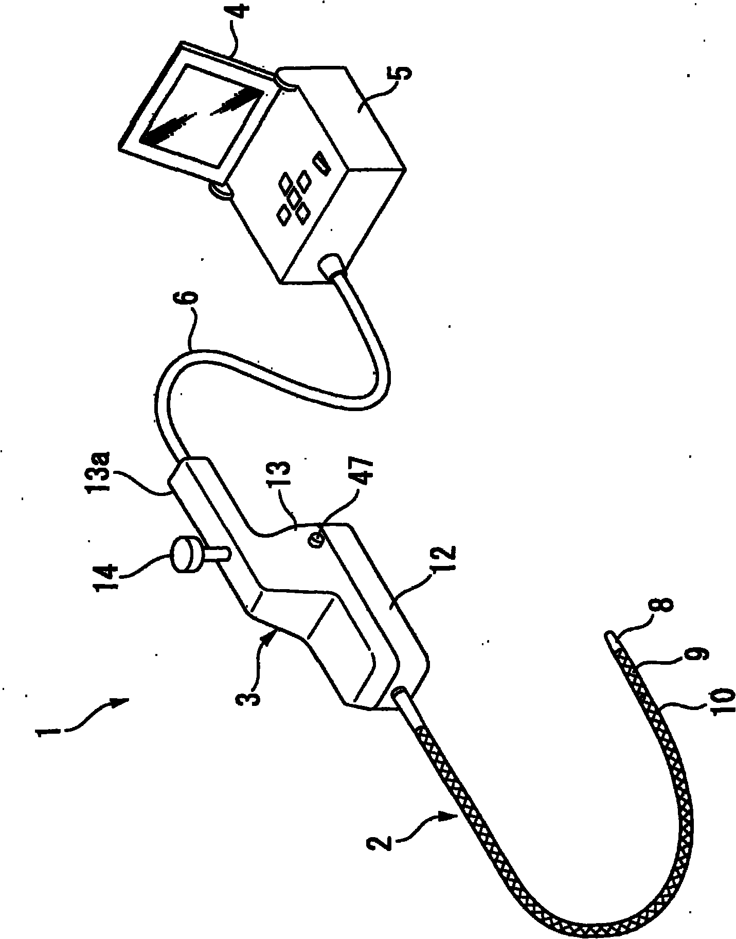
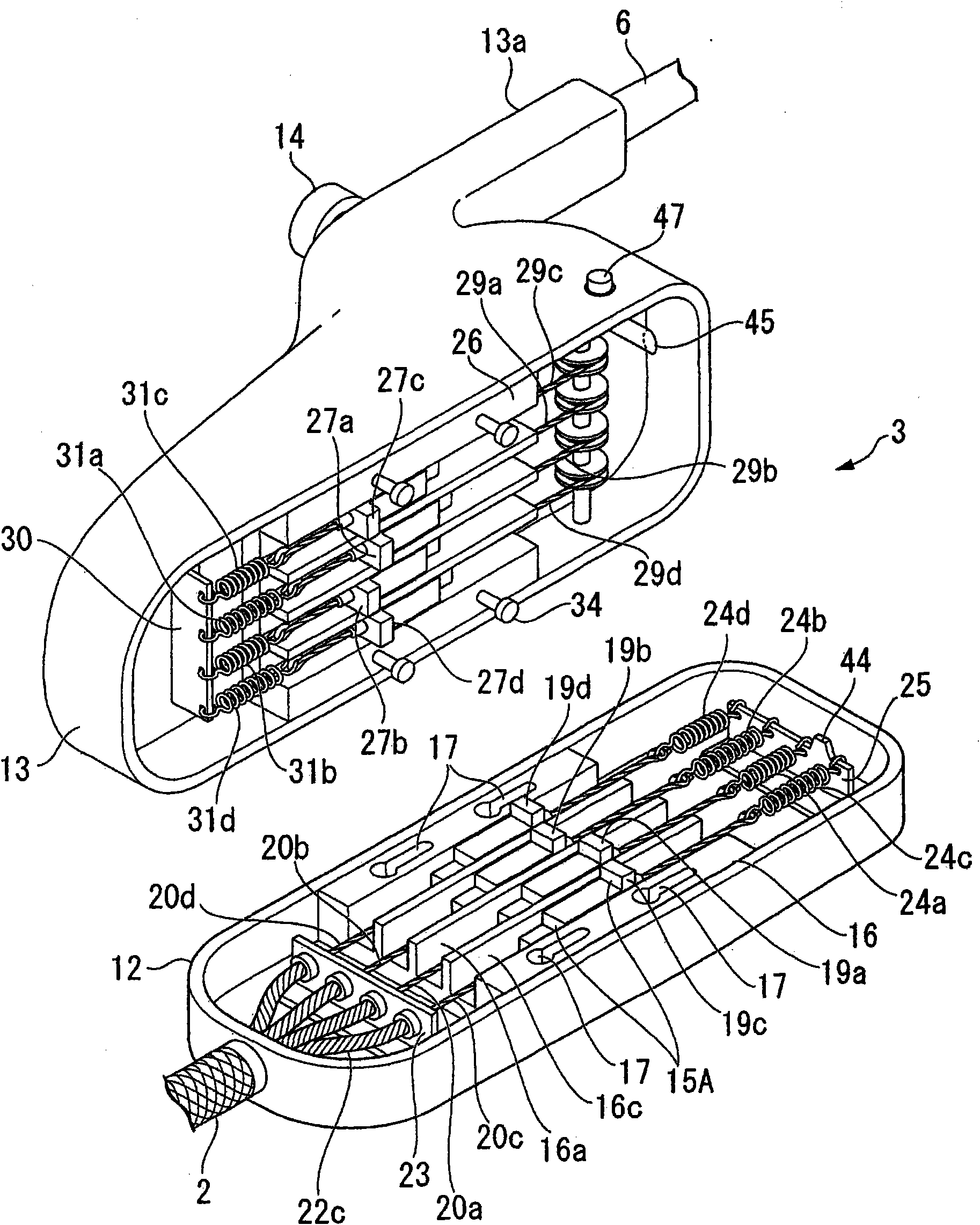
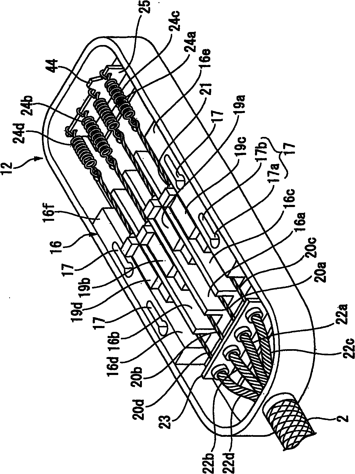
[0071] according to Figure 1 to Figure 13 The endoscope apparatus according to the first embodiment of the present invention will be described. figure 1 is a diagram showing the overall configuration of the endoscope device according to the first embodiment, figure 2 It is a disassembled perspective view of the operation part, image 3 and Figure 4 It is a figure showing the wire connection structure of the insertion part side case, Figure 5 and Image 6 is a diagram showing the wire connection structure of the main body side case, Figure 7A and Figure 7B It is a three-dimensional view of the main part of the joystick and its exploded view, Figure 8A and Figure 8B It is a figure showing the locking structure of the insertion part side case and the main body side case, Figure 9 and Figure 10 It is a figure showing the structure of the operat...


PUM


Abstract

An operation section of an endoscope includes an insertion section-side housing (12) having an insertion section (2) with a curve section, a body-side housing (13), and an operation lever (14) for operating the curve section. The insertion section-side housing has wires (20a-20d) for curving the curve section, first engagement members (19a-19d) capable of advancing and receding in the longitudinal direction, and coil springs (24a-24d). The body-side housing has operation wires (29a-29d) connected to the operation lever, second engagement sections (27a-27d) connected to the operation wires, capable of advancing and receding in the longitudinal direction, and engageable with the first engagement member, and coil springs (31a-31d). When the insertion section-side housing and the body-side housing are slid to be engaged with each other, the first engagement member and the second engagement members are engaged with each other and transmit movement of the operation lever to the curve section of the insertion section. The insertion section-housing can be replaced without positioning it to the body-side housing.

Description

technical field [0001] The present invention relates to an endoscope device for bending an insertion portion of an endoscope or other treatment instruments. [0002] This application claims priority based on Patent Application No. 2007-235475 for which it applied to Japan on September 11, 2007, and uses the content here. Background technique [0003] Conventionally, there are inventions described in Patent Documents 1 and 2 as an apparatus for replacing an insertion portion of an endoscope or other treatment instruments, for example. In these devices, two sets of wires are connected to the curved portion of the insertion portion, and each set of wires is pulled or loosened to bend the curved portion on the front end side in the left-right direction, up-down direction, or the like. In such an endoscope, etc., the distal end portion including the insertion portion can be separated from the main body at the connection portion for replacement, and another type of distal end por...

Claims


Application Information

Patent Timeline
Patent Type & Authority Applications(China)
IPC IPC(8): A61B1/00G02B23/24
CPCA61B1/0057A61B1/0052G02B23/2476A61B1/00128A61B1/0051A61B1/0016A61B1/00042
Inventor 此村优
Owner OLYMPUS CORP
Why Eureka
Try Eureka