
Power assist apparatus and control method thereof

一种动力辅助、设备的技术,应用在程序控制机械手、制造工具、载荷吊挂元件等方向,能够解决工件破损、搬运效率降低、再次操作手柄等问题,达到防止破损的效果

Inactive Publication Date: 2010-08-04
TOYOTA JIDOSHA KK
View PDF2 Cites 3 Cited by
  • Summary
  • Abstract
  • Description
  • Claims
  • Application Information

AI Technical Summary

Problems solved by technology

[0007] In addition, if the posture of the workpiece is fixed in a state where the workpiece is largely inclined relative to the posture desired by the operator, the workpiece may contact the peripheral portion of the transport path of the workpiece or the mounting object member of the workpiece, causing damage to the workpiece
Also, in this case, the operator must operate the handle again after releasing the brake mechanism to modify the posture of the workpiece to the posture desired by the operator
Therefore, the transfer efficiency will decrease

Method used


Image

  • Power assist apparatus and control method thereof
  • Power assist apparatus and control method thereof
  • Power assist apparatus and control method thereof

Examples


Embodiment Construction

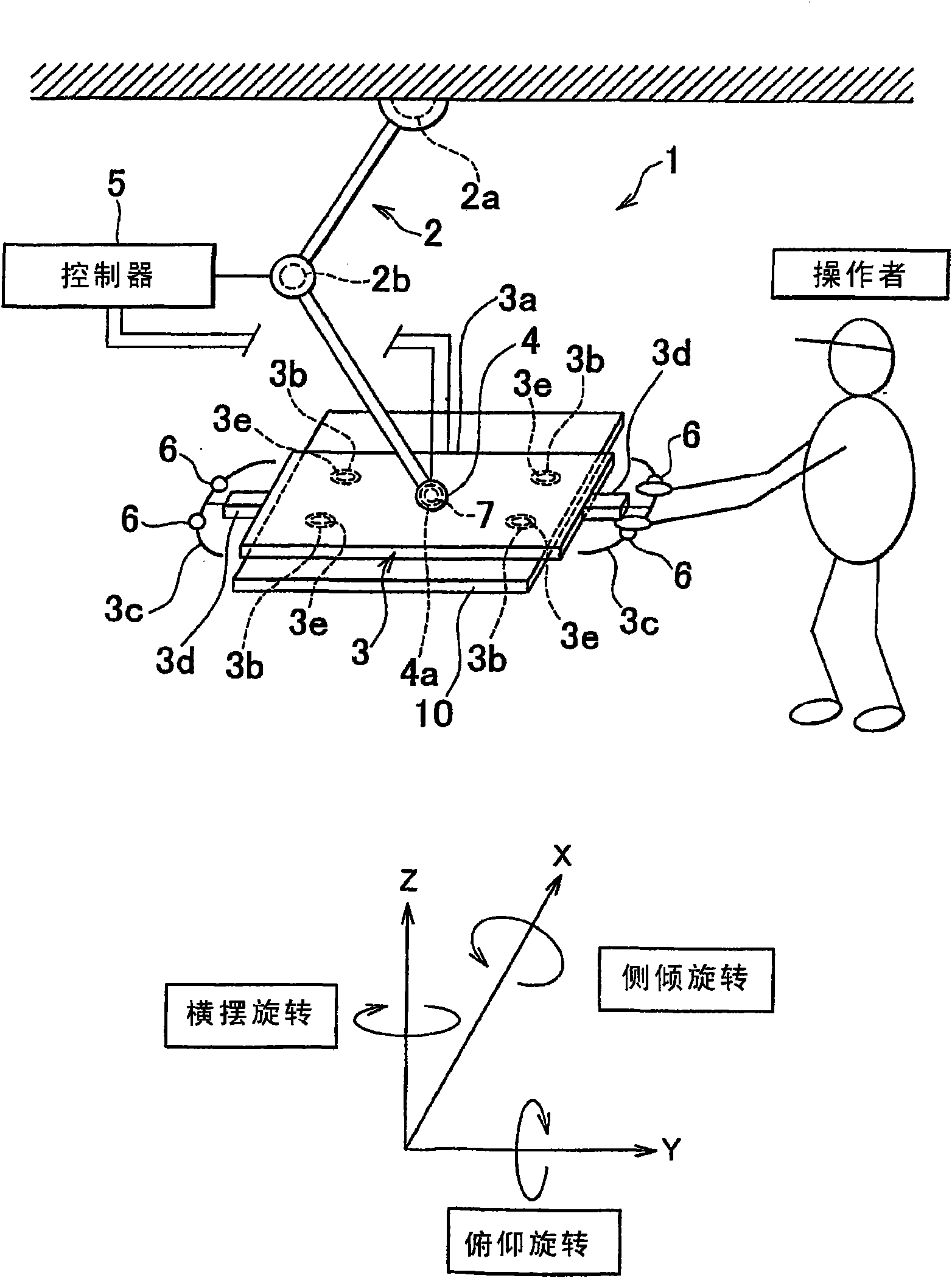
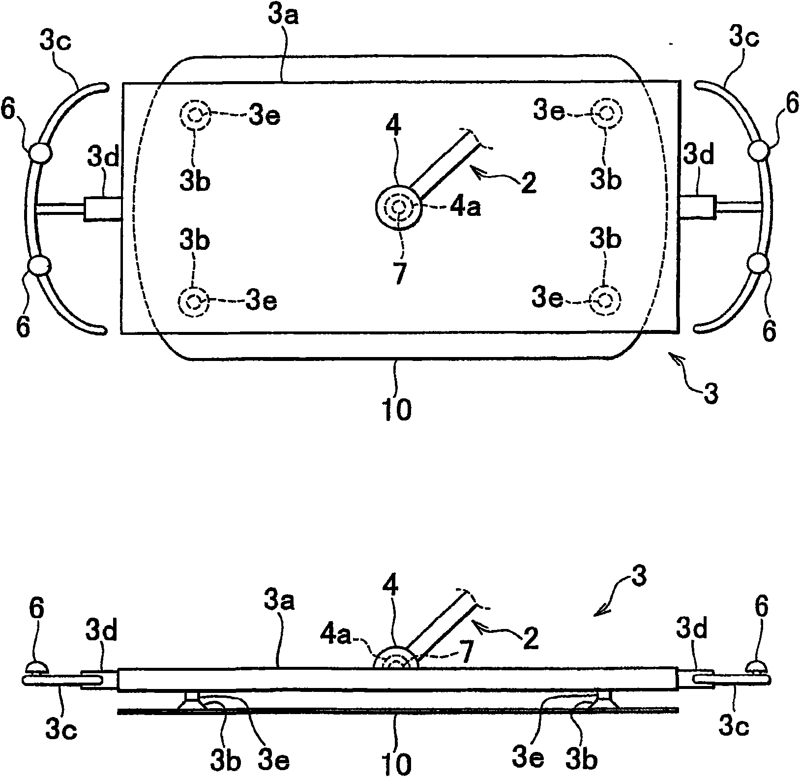
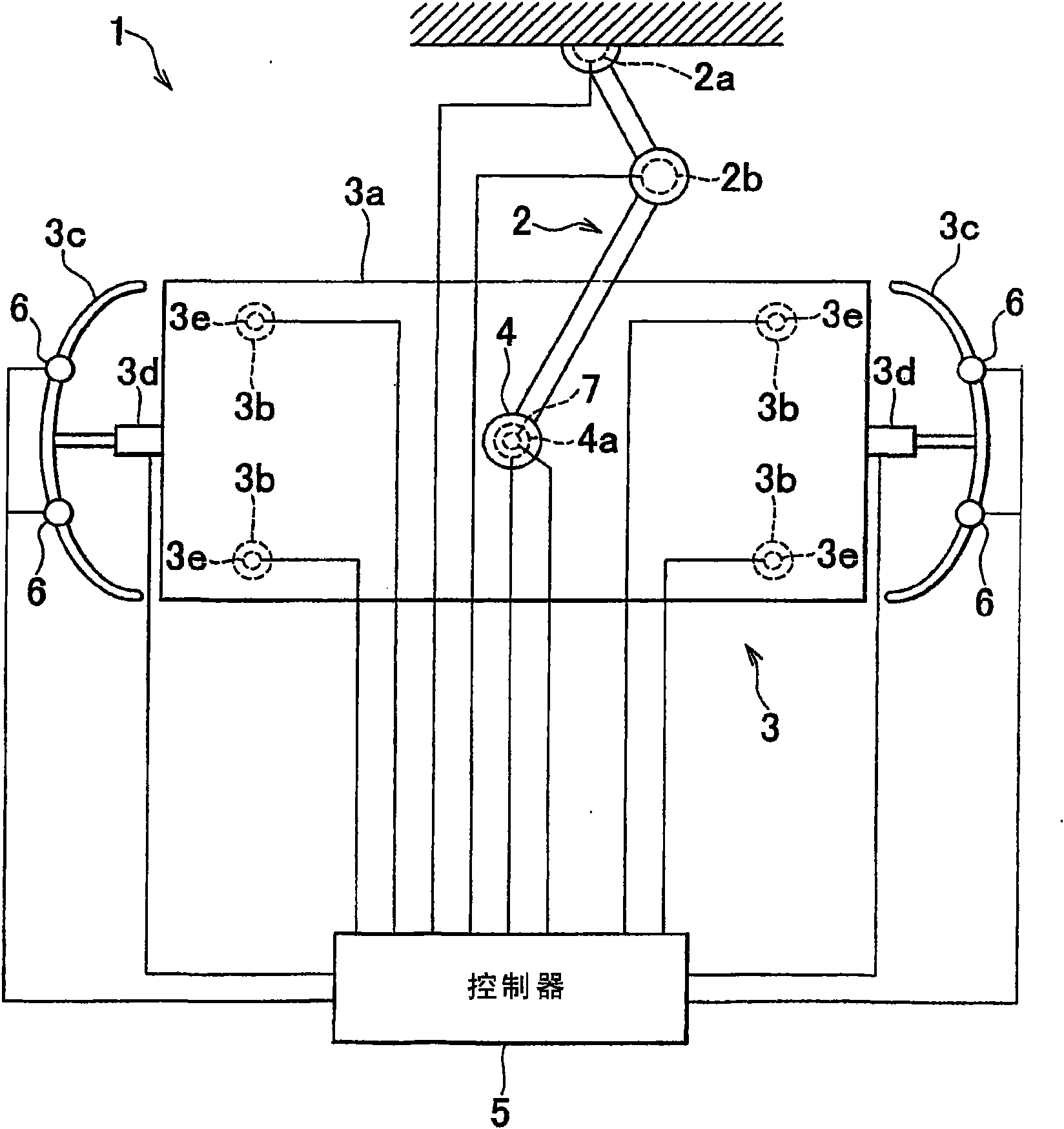
[0031] First, we will use Figure 1 to Figure 3 The overall configuration of the power assist device 1 according to the embodiment of the present invention is described. figure 1 It is a schematic diagram showing the overall configuration of a power assist device according to an embodiment of the present invention. figure 2 It is a schematic plan view and a schematic side view showing a workpiece holding device according to an embodiment of the present invention. image 3 It is a schematic diagram showing the connection status of the controller according to the embodiment of the present invention. Note that for ease of description, it is assumed that the power assist equipment is set in figure 1 In the XYZ coordinate system shown, rotation around the X axis represents roll rotation, rotation around the Y axis represents pitch rotation, and rotation around the Z axis represents yaw rotation. Such as figure 1 As shown, the power assist device 1 according to this embodiment include...


PUM


Abstract

If the rotation angle (Theta) in a rotation direction allowed by a joint portion (4) detected by the angle sensor (7) is no more than a predetermined lower limit (ThetaL) or no less than a predetermined upper limit (ThetaH), the controller (5) maintains the released state of the brake mechanism (4a) so that the rotation of the workpiece (10) in the direction is not restricted.

Description

Technical field [0001] The invention relates to power assist equipment and a method for power assist equipment. Background technique [0002] At manufacturing sites for manufacturing industrial products, power assist equipment is used as equipment for assisting operators in carrying heavy objects (workpieces). Workpiece installation operations include the handling and positioning of the work piece, but when the operator and the power assist equipment cooperate to move the work piece, the power required to move the work piece is provided by the power assist equipment. In addition, by adjusting the power assist equipment, the positioning of the workpiece can be effectively performed. Therefore, by using the power assist device, the workload of the operator can be reduced, and the operability can be improved. [0003] A power assist device can be obtained that has a workpiece holding device for holding a workpiece to be conveyed. The workpiece holding device is provided with a hand...

Claims


Application Information

Patent Timeline
Patent Type & Authority Applications(China)
IPC IPC(8): B25J9/16B25J19/00
CPCB66C1/0243B66C23/005B66C1/0256B25J19/0004B25J9/1674Y10T29/53961
Inventor 村山英之
Owner TOYOTA JIDOSHA KK
Features
  • Generate Ideas
  • Intellectual Property
  • Life Sciences
  • Materials
  • Tech Scout
  • Unparalleled Data Quality
  • Higher Quality Content
  • 60% Fewer Hallucinations
Learn More