Valve component

A technology of valve components and shell parts, which is applied in the field of valve components, can solve the problems of expensive construction methods, high manufacturing costs of external threads and internal threads, and high assembly costs, and achieve the effects of simplifying the assembly process, saving costs, and saving costs

Inactive Publication Date: 2010-08-04
欧文韦 +1
View PDF4 Cites 11 Cited by
  • Summary
  • Abstract
  • Description
  • Claims
  • Application Information

AI Technical Summary

Problems solved by technology

However, this construction is relatively expensive, because the outer thread and the inner thread are expensive to manufacture, and in particular several O-rings are required for mutual sealing of the housing part and the installed valve, which O-rings The ring is inserted into the corresponding groove or notch
Therefore, the assembly cost is also quite high

Method used


Image

  • Valve component
  • Valve component
  • Valve component

Examples


Embodiment Construction

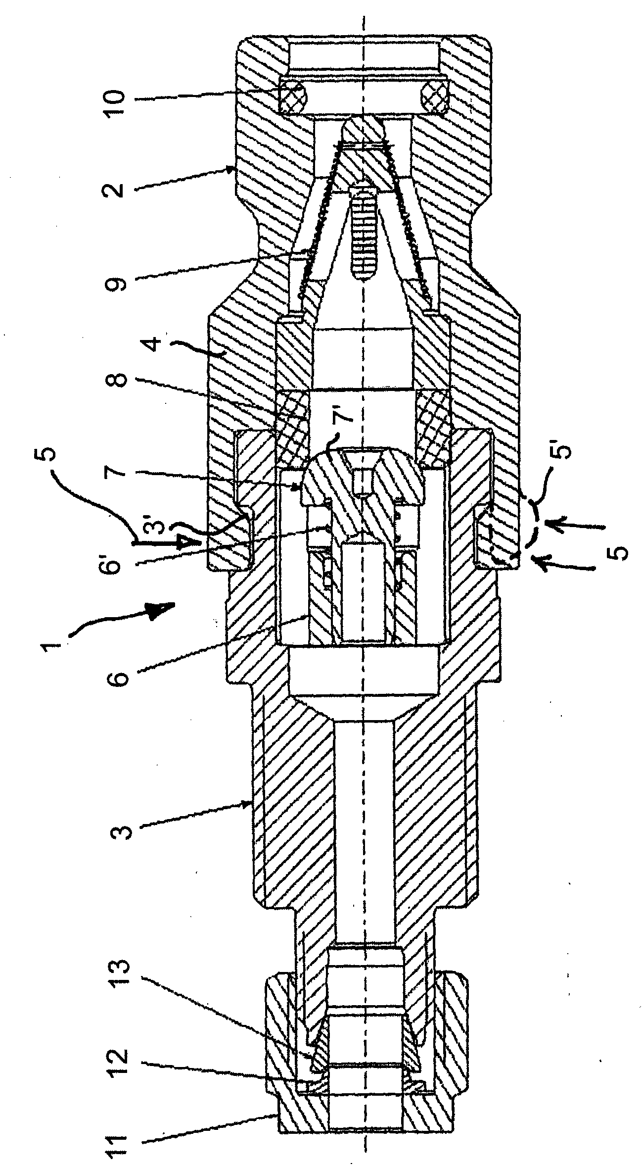
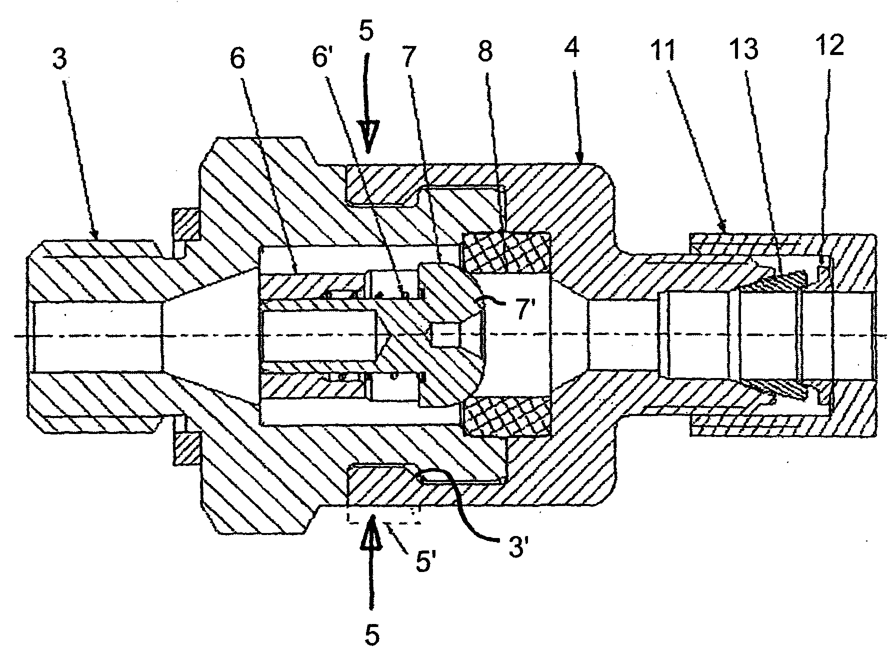
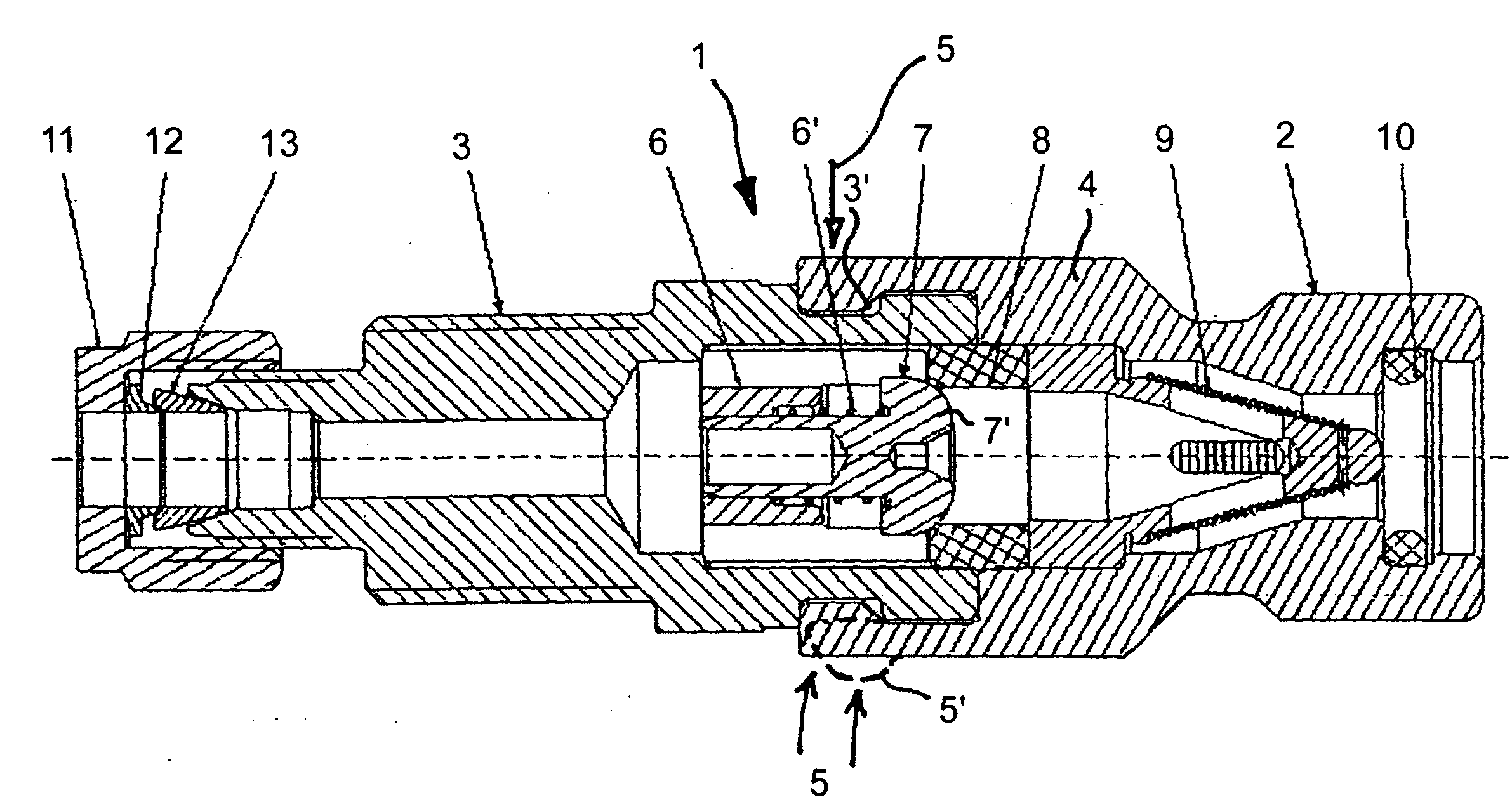
[0011] exist figure 1 A half-section of the valve member 1 in the form of a connecting sleeve is shown in . The connection sleeve has a connection profile 2 for receiving a plug connector, on which a plug connector is positively connected for a pressure-tight connection, as disclosed by the applicant in EP 1 271 039 Show. The valve component 1 is composed of two main components, ie two sleeve-shaped housing parts 3 , 4 , which are securely connected to each other by means of a pinch (as indicated by arrow 5 ). For this reason, a ring groove 3 ′ is turned on one of the two housing parts (the left housing part 3 here), and after the housing part 4 is sleeved on the housing part 3, the A milled or turned bead 5 ′ (shown in dashed lines in the lower region) is pressed into the ring groove 3 ′. The two housing parts 3 and 4 are thus securely and stably connected via the extrusion or flange 5 .

[0012] A sealing sleeve 8 is also securely clamped in the interior of the connectin...


PUM


Abstract

For the simple and cost-effective production of a valve component (1) in the form of a non-return valve or a connecting nipple, in particular for the refuelling of natural gas vehicles, or for the pressure-tight connection to a fluid line or a plug-in coupling, wherein the valve component (1) has two housing parts (3, 4) which are connected pressure-tightly to each other and accommodate a valve (7) there within, it is proposed that the housing parts (3, 4) are pressed together at an annular groove (3').

Description

technical field [0001] The invention relates to a valve component in the form of a non-return valve or a connection sleeve, in particular for supplying fuel to natural gas vehicles, which has the features of the preamble of claim 1 . Background technique [0002] The applicant discloses a connecting sleeve of this type in WO 00 / 52378. In this case, a plug-in connector is described, which abuts on a connecting sleeve, wherein clamps engage in the connecting sleeve. This results in a form-fitting and pressure-tight connection, which is required for pressurized filling of natural gas vehicles with higher pressures. The connecting sleeve is subjected to relatively high loads here, so it must be designed to be very stable in order to comply with the standards for gas filling (NGV). [0003] Such connecting sleeves are usually screwed together by two sleeve-shaped housing parts in which a valve with corresponding sealing surfaces is inserted. However, this construction is relat...

Claims


Application Information

Patent Timeline
Patent Type & Authority Applications(China)
IPC IPC(8): F16K15/06F16K27/02
CPCF16K15/026F16L13/141F16K15/063F17C2205/037F16L29/02F16K27/0209F16K25/005
Inventor 欧文·韦沃尔夫冈·韦
Owner 欧文韦
Why Eureka
Try Eureka