Zero-heat differential phase shift keying demodulator

A differential phase shift keying and demodulator technology, applied in optical demodulation, instruments, electromagnetic wave transmission systems, etc., can solve problems such as being very sensitive to temperature changes and unfavorable center frequency adjustment

Inactive Publication Date: 2010-08-11
ZHUHAI FTZ OPLINK COMM
View PDF6 Cites 6 Cited by
  • Summary
  • Abstract
  • Description
  • Claims
  • Application Information

AI Technical Summary

Problems solved by technology

However, when this differential phase shift keying demodulator adjusts the center frequency, the temperature of the light-transmitting member 27 cha...

Method used


Image

  • Zero-heat differential phase shift keying demodulator
  • Zero-heat differential phase shift keying demodulator
  • Zero-heat differential phase shift keying demodulator

Examples


no. 1 example

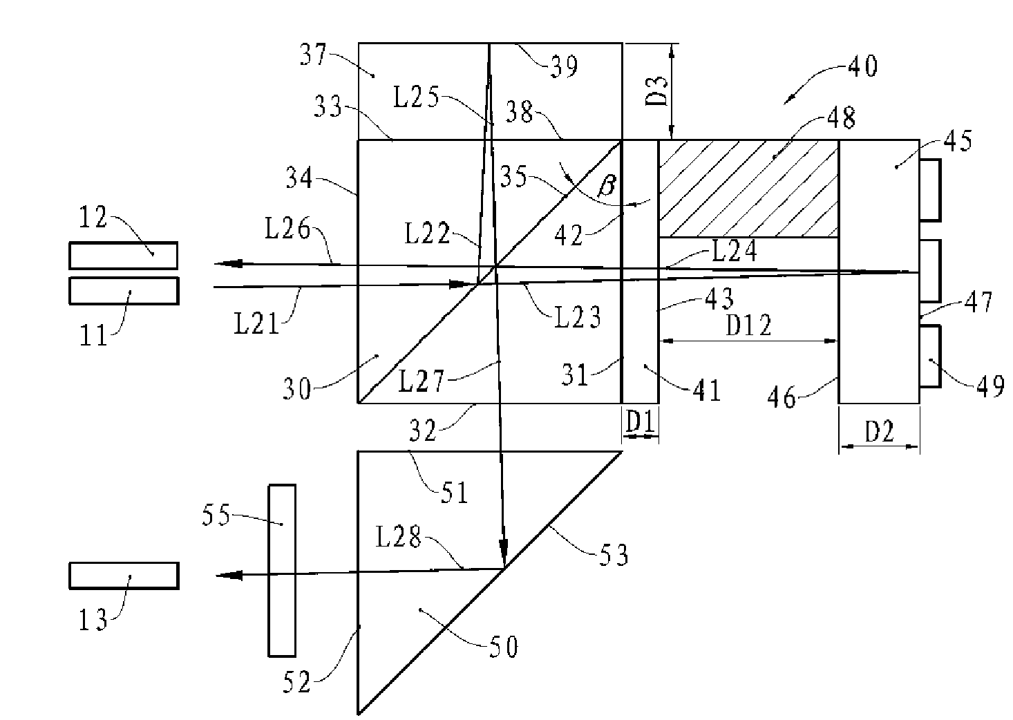
[0028] see figure 2 , this embodiment has an input port 11, a first output port 12, and a second output port 13, and the three ports are arranged on the same side. The present embodiment is also provided with a beam splitter 30, the cross section of the beam splitter 30 is rectangular, one of its diagonals forms a beam splitting surface 35, the beam splitting surface 35 is a 50:50 beam splitting film, and the light beam incident on the beam splitting surface 35 is as follows The ratio forms the transmitted beam and the reflected beam.

[0029] One end surface of the beam splitter 30 is the first light-transmitting surface 31 , and the angle β formed between the first light-transmitting surface 31 and the light-splitting surface 35 is 45°. An end surface perpendicular to the first light-transmitting surface 31 is the second light-transmitting surface 32, the end surface opposite to the second light-transmitting surface 32 is the third light-transmitting surface 33, and the en...

no. 2 example

[0050] Same as the first embodiment, this embodiment has one input port and two output ports, and is provided with a beam splitter, and the beam splitter is provided with a light splitting surface and four light-transmitting surfaces, and outside the first light-transmitting surface is provided For the interference arm etalon, a reflective prism and a phase retardation film are arranged outside the second light-transmitting surface, and a compensation film is arranged outside the third light-transmitting surface, which will not be repeated here.

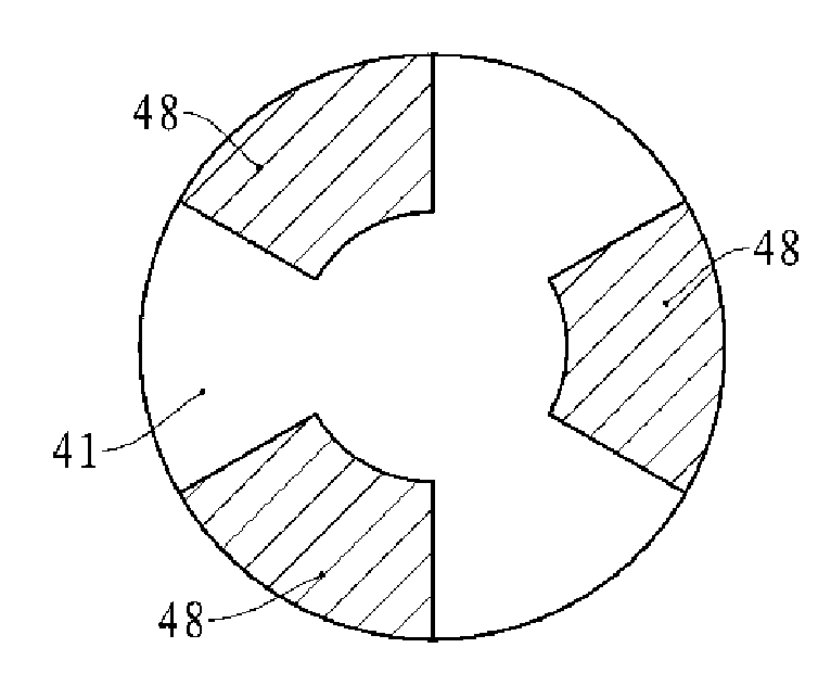
[0051] see Figure 4 , the interference arm etalon 60 of the present embodiment has a first optical glass 61 and a second optical glass 62, and a partition made of a material insensitive to temperature change is arranged between the first optical glass 61 and the second optical glass 62 68. The partition 68 in this embodiment is an annular body, which is continuously distributed in the circumferential direction between the first opt...

no. 3 example

[0054] Same as the first embodiment, this embodiment also has an input port and two output ports, and is provided with a beam splitter, an interference arm etalon, a compensation sheet, and a reflection prism, etc. The structure of the interference arm etalon of this embodiment is as follows Figure 5 shown.

[0055] The interference arm etalon 70 has a first optical glass 71 and a second optical glass 75, the cross section of the first optical glass 71 is wedge-shaped, and it has an outer surface 72 and an inner surface 73, the outer surface 71 and the first light transmission of the beam splitter Face to face, the plane where the inner surface 73 is located intersects the plane where the outer surface 71 is located, that is, the plane where the inner surface 73 is located intersects the plane where the first light-transmitting surface of the beam splitter is located.

[0056] The second optical glass 75 also has an outer surface 77 and an inner surface 76 , the inner surface...


PUM


Abstract

The invention provides a zero-heat differential phase shift keying demodulator, which comprises an input port, a first output port and a second output port, and is provided with an optical splitter, wherein the optical splitter is provided with an optical splitting surface and a first transparent surface at an included angle of 45 degrees to the optical splitting surface. The demodulator is also provided with an interference arm instrument with first optical glass and second optical glass arranged in parallel with each other. A separator made of a material insensitive to temperature variation is arranged between the first optical glass and the second optical glass; the outer surface of the first optical glass is in butt joint with the first transparent surface of the optical splitter; and a phase adjustment controller is also arranged on the outer surface of the second optical glass and is used for changing the thickness or index of refraction of the second optical glass. The zero-heat differential phase shift keying demodulator provided by the invention can adjust centre frequency for the output of optical signals and the adjustment of the centre frequency is insensitive to the variation of an environmental temperature.

Description

technical field [0001] The invention relates to a differential phase-shift keying demodulator, in particular to an athermal differential phase-shift keying demodulator for optical fiber network. Background technique [0002] With the development of network communication, the data transmission speed of the optical fiber network is getting faster and faster, and the requirement for the capacity of the optical fiber network is also getting higher and higher. In the current high-speed optical fiber network system, most of the differential phase shift keying technology is used to convert the modulation mode of the optical signal from phase modulation to intensity modulation. Therefore, it is necessary to use a differential phase shift keying demodulator to realize the conversion of the above modulation mode. [0003] The structural schematic diagram of an existing differential phase shift keying demodulator is as follows: figure 1 As shown, it has an input port 11 and two output...

Claims


Application Information

Patent Timeline
IPC IPC(8): G02F2/00H04B10/158H04B10/556
Inventor 杜勇陈国平
Owner ZHUHAI FTZ OPLINK COMM
Why Eureka
Try Eureka