Supercharge Your Innovation With Domain-Expert AI Agents!

Redundant hardware architecture for the control signal stage of a braking system for a vehicle all the wheels of which are each connected to at least one rotary electrical machine

A technology of rotating motors and control signals, which is applied in the field of road vehicle systems and can solve problems such as electric brakes that are not mentioned

Inactive Publication Date: 2013-06-26
OCIETE DE TECH MICHELIN +1
View PDF7 Cites 0 Cited by
  • Summary
  • Abstract
  • Description
  • Claims
  • Application Information

AI Technical Summary

Problems solved by technology

Said patent does not mention the control of electric braking

Method used


Image

  • Redundant hardware architecture for the control signal stage of a braking system for a vehicle all the wheels of which are each connected to at least one rotary electrical machine
  • Redundant hardware architecture for the control signal stage of a braking system for a vehicle all the wheels of which are each connected to at least one rotary electrical machine
  • Redundant hardware architecture for the control signal stage of a braking system for a vehicle all the wheels of which are each connected to at least one rotary electrical machine

Examples


Embodiment Construction

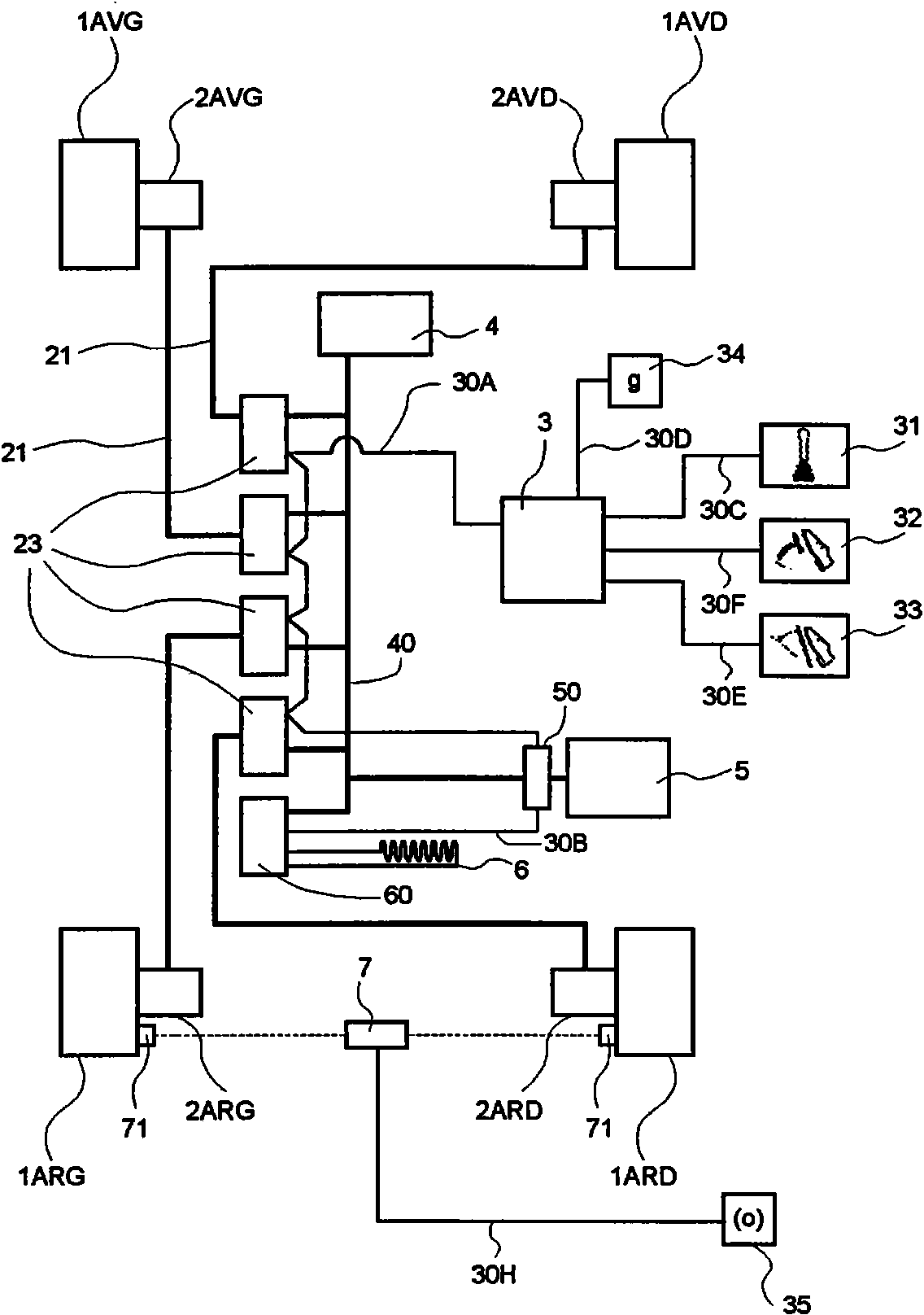
[0031] figure 1 is schematically shown with four wheels 1 AvG ,1 AvD ,1 ArG and 1 ArD Vehicles. Wheels are labeled 1 AvG Indicates the left front wheel, 1 AvD Indicates the right front wheel, 1 ArG Indicates the left rear wheel, 1 ArD Indicates the right rear wheel. Each wheel is equipped with an electric motor mechanically coupled to it. Motor 2 AvG ,2 AvD ,2 ArG and 2 ArD is shown. In the following, subscripts specifically indicating the positions of the wheels 1 or the motor 2 in the vehicle are not repeated when they have no effect on the clarity of the description in this specification. The electric traction machine 2 is a three-phase synchronous motor equipped with resolver-type angular position sensors and driven by wheel drive electronics modules 23 to which they are connected via power supply lines 21 . The wheel drive electronics module 23 is designed to be able to drive the electric motor in terms of torque. Each wheel drive electronics module 23 can...


PUM


Abstract

System for electrical braking of a road vehicle of which at least one wheel is linked in rotation to at least one rotary electric machine, at least one wheel drive electronic module 23 driving the electric machine or machines of one and the same wheel, comprising a central unit 3 ensuring the management of the movement of the vehicle, the said central unit controlling the wheel drive electronic module or modules 23, comprising a braking control at the disposal of a driver, the said control being linked mechanically at least to three sensors C1, C2, C3 delivering a control signal for braking the vehicle having a given amplitude representative of the total braking force desired for the vehicle, the said sensors C1, C2, C3 being distributed into a first group C1 and a second group C2, C3, in which the sensor (sensors) C1 of the first group delivers (deliver) its (their) control signal to the said central unit 3 and the sensor (sensors) of the second group C2, C3 delivers (deliver) its (their) control signal to the or to each of the wheel drive electronic modules 23.

Description

technical field [0001] The invention relates to road vehicles. It relates in particular to systems for braking electric traction road vehicles. Background technique [0002] Electric vehicles include vehicles in which electric energy necessary for its movement is stored in a battery, and vehicles in which electric energy is generated on-board by an engine-driven generator or by a fuel cell. The traction of the vehicle is ensured by one or more electric motors. The braking of the vehicle is ensured by a conventional mechanical braking system. The prior art already contains a very large number of proposals for electric traction vehicles. One can cite, for example, US Patent 5,418,437, which describes a series of hybrid four-wheeled vehicles, each wheel being driven by its own dedicated electric motor, a controller making it possible to drive the wheel motors and ensuring power from the alternator or battery to the motors supply control. Said patent is silent on the contro...

Claims


Application Information

Patent Timeline
Patent Type & Authority Patents(China)
IPC IPC(8): B60L3/00B60L7/00B60L15/36H02P3/06
CPCB60L2200/26B60L3/0092B60L2260/28B60L3/0038B60L7/22B60L7/26B60L3/102B60L2250/10
Inventor G·布尔吉F·丘德-莫鲁J-L·琳达
Owner OCIETE DE TECH MICHELIN
Features
  • R&D
  • Intellectual Property
  • Life Sciences
  • Materials
  • Tech Scout
  • Unparalleled Data Quality
  • Higher Quality Content
  • 60% Fewer Hallucinations
Learn More