Waste collection facility with storage tank and service space

A technology for collecting equipment and overhauling space, which is applied in the field of waste collection equipment and can solve problems such as water seepage

Inactive Publication Date: 2010-08-11
EHNVAK AB
View PDF0 Cites 2 Cited by
  • Summary
  • Abstract
  • Description
  • Claims
  • Application Information

AI Technical Summary

Problems solved by technology

At present, plastic containers are generally used to achieve this purpose, but the problem of water seepage also occurs at the same time

Method used


Image

  • Waste collection facility with storage tank and service space
  • Waste collection facility with storage tank and service space
  • Waste collection facility with storage tank and service space

Examples


Embodiment Construction

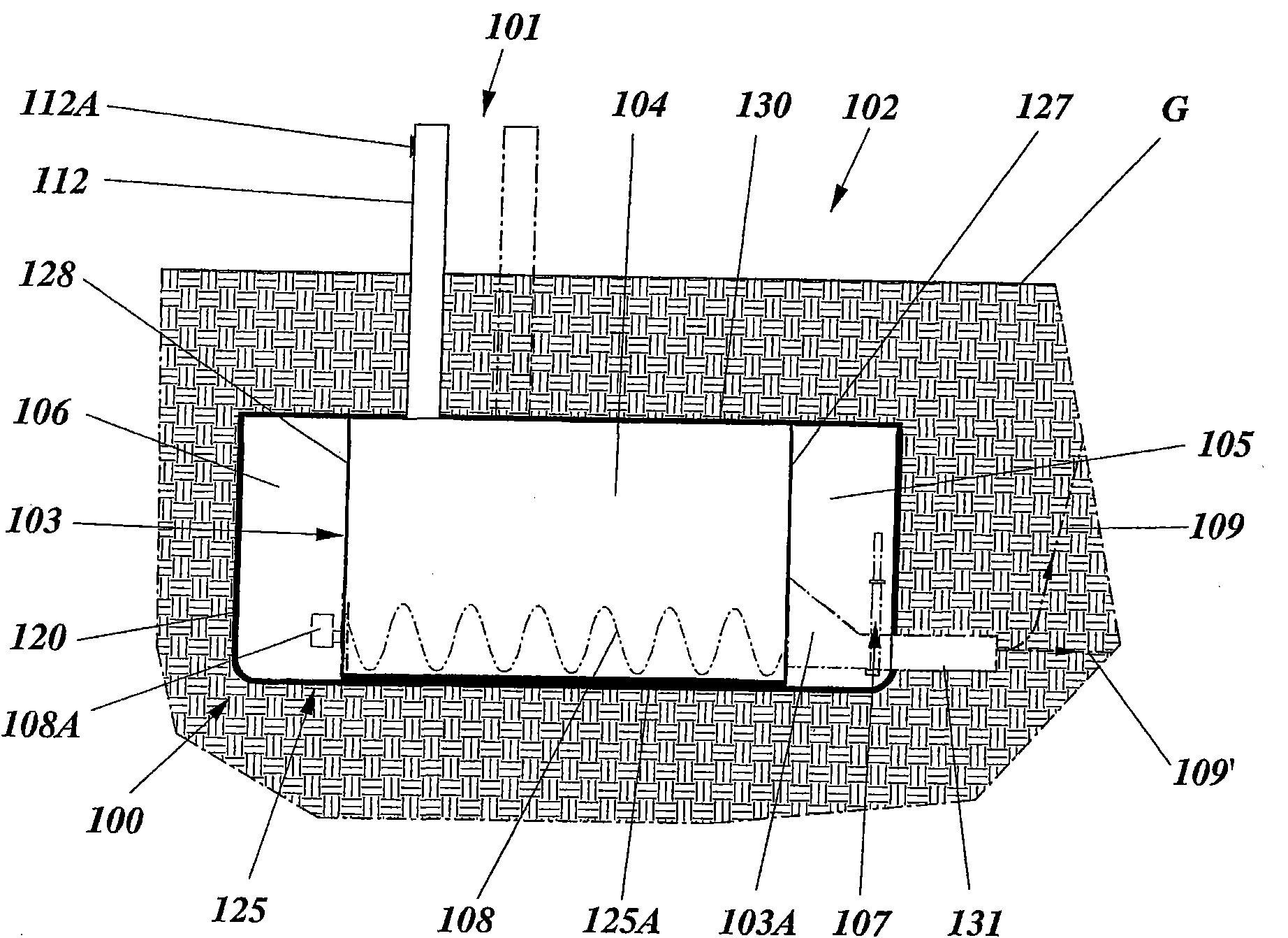
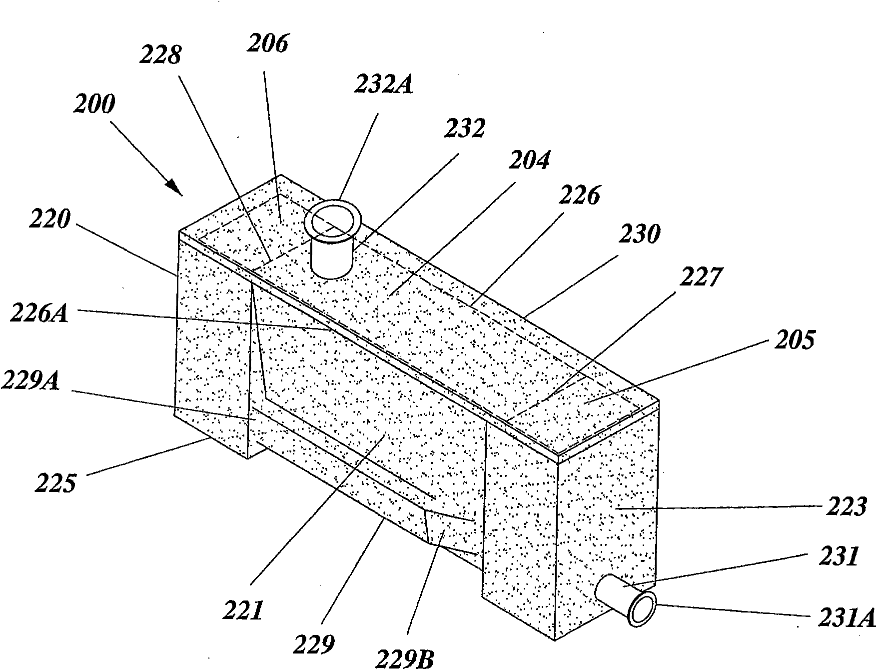
[0024] Reference will now be made to an illustrative embodiment of the waste collection apparatus of the present invention, described with reference to the accompanying Figure 2-6 Make a diagram. The illustrative embodiment shown in the figures relates to the application of the invention to a waste collection system comprising an underground temporary waste storage tank having a screw-shaped agitator device. It should be emphasized that the illustration is for the purpose of describing a preferred embodiment of the invention and is not intended to limit the invention to its details.

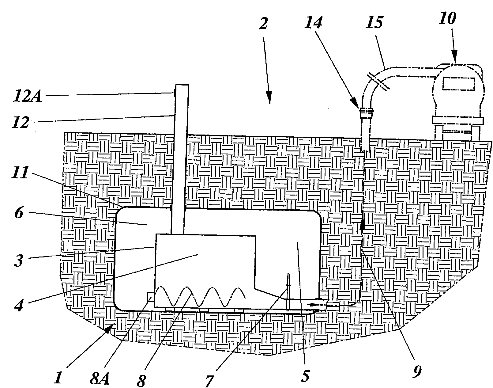
[0025] figure 1 A partial schematic diagram of an example of a conventional vacuum waste collection system 2 is shown, together with the waste collection point 1 in use as described above. Specifically, figure 1 A mobile vacuum operated waste collection system 2 with an underground temporary storage tank 3 is shown. In this system, the waste is deposited by opening the waste inlet 12A provid...


PUM


Abstract

In a waste collection and temporary storage facility (100) that is intended for use in a vacuum operated waste collection system (102) and that includes a waste tank (103) having a waste collection volume (104) with a waste agitating and / or feeding means (108) provided therein, and at least one service space (105, 106) separate from said tank volume, there is provided a base structure (120) delimiting the storage tank (103) and its waste collection volume (104) as well as the at least one service space (105, 106) and at least one divider wall (127, 128) forming an end wall of the tank and separating, inside the structure, the waste collection volume (104) from the at least one service space (105, 106).

Description

technical field [0001] The present invention relates generally to waste collection and in particular to a waste collection apparatus for the temporary storage of waste collected at a waste dump of a vacuum operated waste collection system. Background technique [0002] Today, waste collection systems operated by vacuum operation are widely used, mainly for the collection of household or office waste in residential or residential areas or in the centers of commercial areas, but also for the collection of medical waste, etc. In such systems, stored refuse is transported by air in a system of ducts. Specifically, the stockpiled waste is sucked in from separate, isolated storage points or collection points, and then conveyed to a central collection station (often referred to as a stationary system), or to a vacuum truck (known as a flow system). To meet the continuing need to handle increasing volumes of waste in such systems, it has for many years been relied upon to increase...

Claims


Application Information

Patent Timeline
Patent Type & Authority Applications(China)
IPC IPC(8): B65F1/14
CPCB65F5/005B09B5/00B61D5/08B65F5/00
Inventor 马格努斯·埃科尔姆
Owner EHNVAK AB
Why Eureka
Try Eureka