Supercharge Your Innovation With Domain-Expert AI Agents!

Hot-dip coating installation

A hot-dip plating and equipment technology, applied in hot-dip plating process, mechanical equipment, coating and other directions, can solve problems such as damage to the surface of the strip, and achieve the effect of eliminating the possibility of deformation

Inactive Publication Date: 2012-08-08
SMS DEMAG AG
View PDF1 Cites 0 Cited by
  • Summary
  • Abstract
  • Description
  • Claims
  • Application Information

AI Technical Summary

Problems solved by technology

This difference in movement speed causes damage to the strip surface

Method used


Image

  • Hot-dip coating installation
  • Hot-dip coating installation

Examples


Embodiment Construction

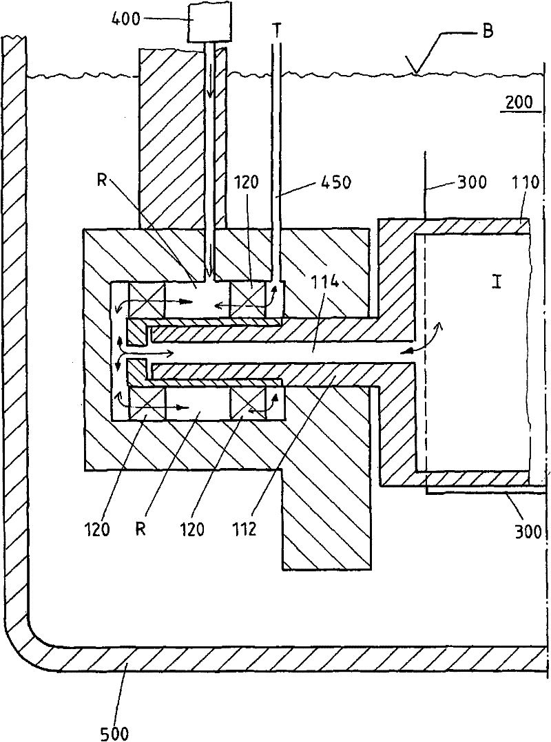
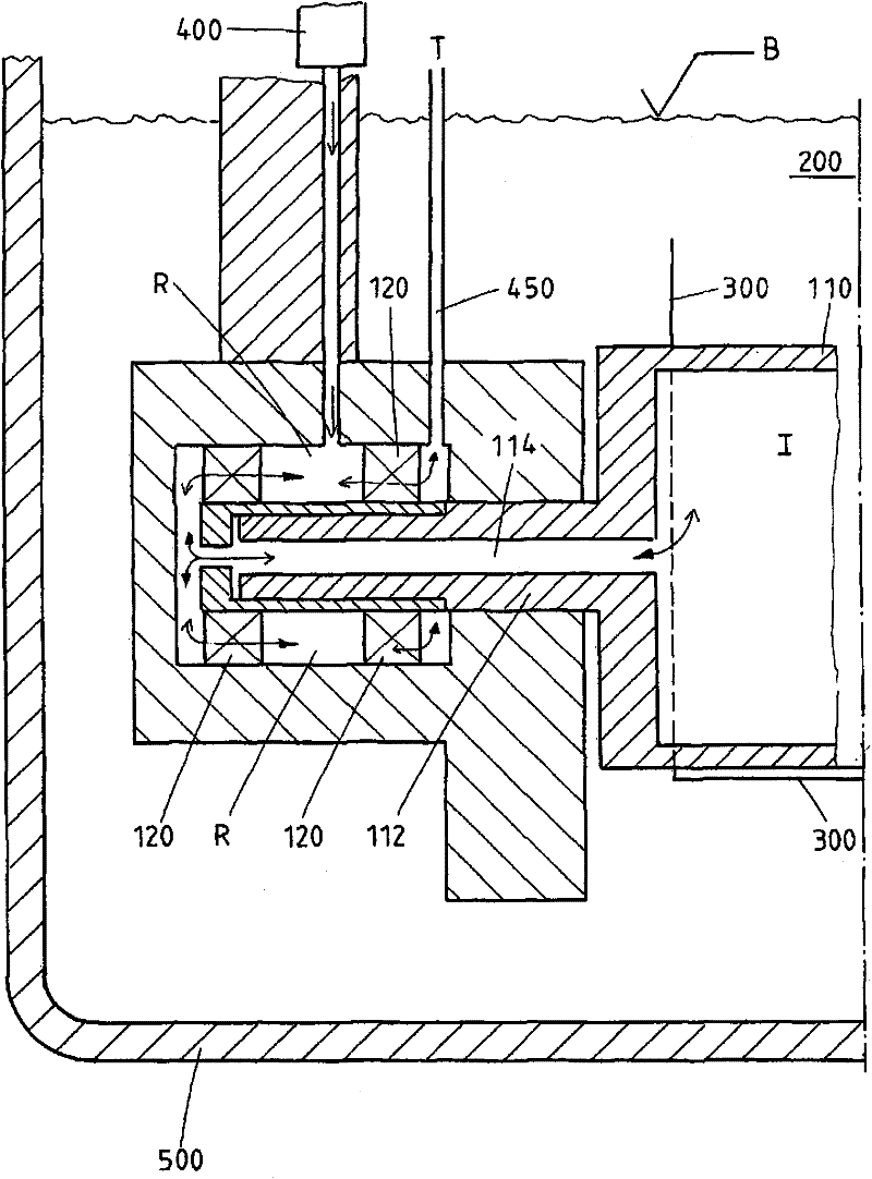
[0014] Hereinafter, the present invention will be described in detail in the form of embodiments with reference to the accompanying drawings.

[0015] The drawing shows a cross-section through a hot-dip coating installation for coating a strip 300 , in particular steel strip, with a molten metal 200 . The hot-dip galvanizing plant comprises a vessel 500 containing molten metal in which a roll 110 supported on a support arm is immersed. Roller 110 is shown in the drawing, for example, in the form of a deflection roll for deflecting the strip in molten metal 200 . The roll 110 is in the form of a hollow body with an inner cavity I and is sealed against the surrounding molten metal 200 . The roll 110 has a roll neck 112, by means of which the roll is mounted in a bearing 120, preferably a roller bearing. The bearing 120 is arranged on the roll neck circumference and is surrounded by a space region R. As shown in FIG. According to the invention, the interior I of the roller 110...


PUM


Abstract

The invention relates to a hot-dip coating installation for coating a strip with a liquid metal. A roll embodied as a hollow body is provided in the liquid metal for deflecting or stabilising the strip. The roll is mounted in a bearing on a carrier arm of the hot-dip coating installation by means of a journal. The aim of the invention is to reduce the rotational resistance, the angular momentum and the slip incline of the roll in relation to the strip. To this end, the inside of the roll is sealed against the liquid metal and a channel is provided for connecting the inside of the roll to the spatial area on the periphery of the roll journal. In this way, an excess pressure inside the roll and therefore an unwanted deformation of the roll are prevented.

Description

technical field [0001] The invention relates to a hot-dip coating plant for coating strips with molten metal. Background technique [0002] Hot-dip coating plants are basically known in the prior art. In this installation, the strip to be coated, in particular steel strip, is guided through a bath filled with molten metal. In order to guide and influence the strip shape and strip position, there are various rollers at suitable positions in the molten metal bath. On the one hand, the rolls can be deflection rolls around which the strip is deflected after it enters the molten metal and then leaves the bath again. In addition to the deflection rollers, it is also possible to provide a plurality of smaller straightening stabilizing rollers, which are pressed onto the strip with only a relatively smaller wrap angle than the deflection rollers. Due to the small wrap angle, the driving force for the rollers is small. [0003] International patent application WO2006 / 002822, for ...

Claims


Application Information

Patent Timeline
Patent Type & Authority Patents(China)
IPC IPC(8): C23C2/00F16C33/76
CPCF16C13/00C23C2/003C23C2/00344F16C33/76C23C2/40
Inventor P·德科克R·贾布斯
Owner SMS DEMAG AG
Features
  • R&D
  • Intellectual Property
  • Life Sciences
  • Materials
  • Tech Scout
  • Unparalleled Data Quality
  • Higher Quality Content
  • 60% Fewer Hallucinations
Learn More