Exhaust system structure of film forming apparatus, film forming apparatus and method of disposing of exhaust gas

A film-forming device and gas-exhausting technology, which is applied in the fields of greenhouse gas capture, electrical components, and electrical solid devices, can solve troublesome problems and achieve the effect of reducing maintenance man-hours and costs

Inactive Publication Date: 2010-08-11
TOKYO ELECTRON LTD
View PDF1 Cites 4 Cited by
  • Summary
  • Abstract
  • Description
  • Claims
  • Application Information

AI Technical Summary

Problems solved by technology

[0007] Therefore, when using organic metal raw materials, the treatment of the recovery of the trapping mechanism must be carried out extremely carefully. For example, the method of slowly deactivating the recovery by dissolving the recovery in an organic solvent can be adopted, but it is extremely troublesome. There are concerns about toxicity and flammability due to the use of organic solvents

Method used


Image

  • Exhaust system structure of film forming apparatus, film forming apparatus and method of disposing of exhaust gas
  • Exhaust system structure of film forming apparatus, film forming apparatus and method of disposing of exhaust gas
  • Exhaust system structure of film forming apparatus, film forming apparatus and method of disposing of exhaust gas

Examples


no. 1 Embodiment approach

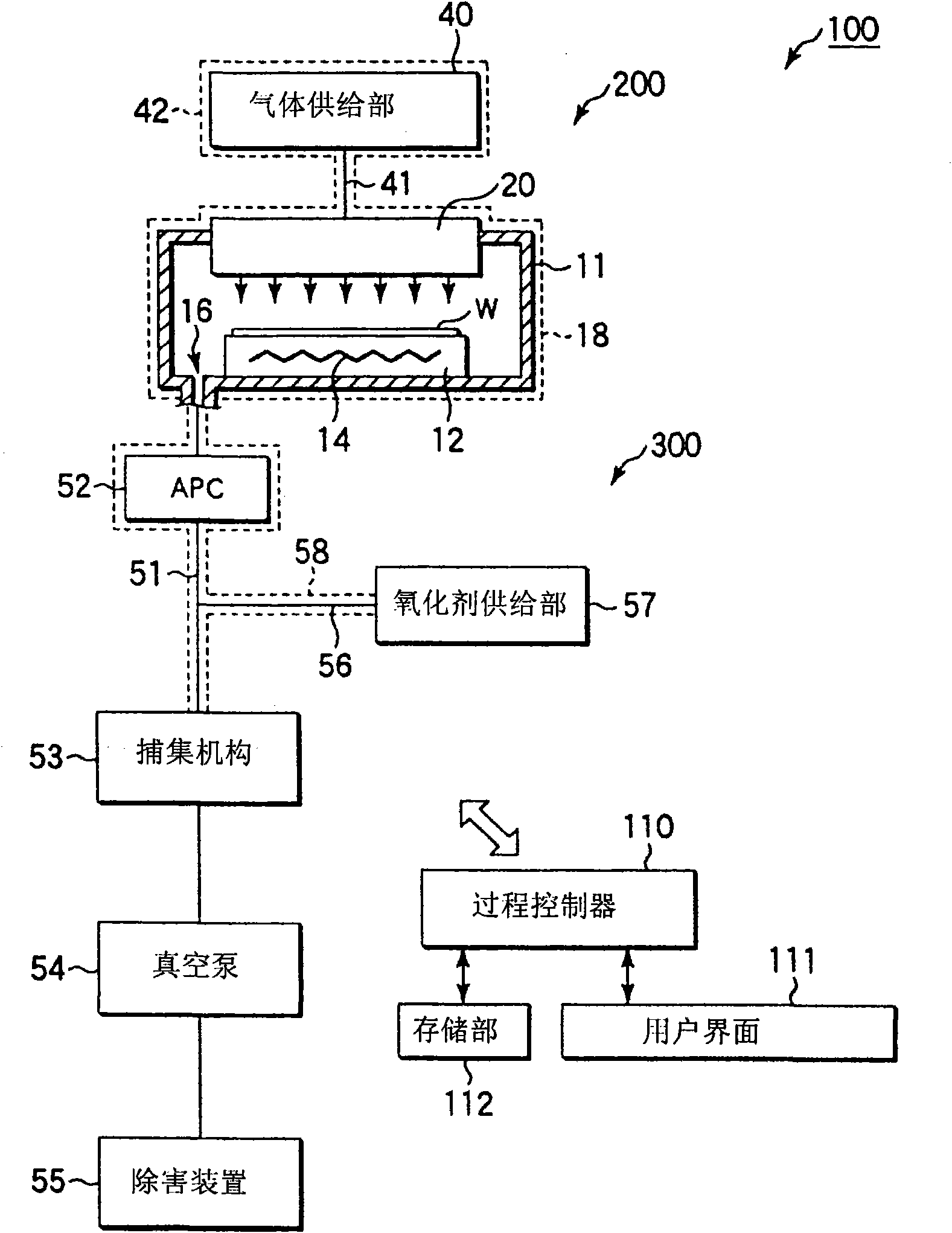
[0024] figure 1 It is a schematic diagram showing a film forming apparatus having an exhaust system structure according to the first embodiment of the present invention. The film forming apparatus 100 is roughly divided into a film forming processing unit 200 and an exhaust system 300 .

[0025] The film formation processing unit 200 has a substantially cylindrical processing chamber 11 . A mounting table 12 for horizontally mounting a wafer W as a substrate to be processed is disposed on the inner bottom of the processing chamber 11 . A heater 14 is embedded in the stage 12, and the heater 14 heats the wafer W serving as a substrate to be processed to a predetermined temperature. An exhaust port 16 is provided on the bottom surface of the processing chamber 11 . In addition, a wafer loading and unloading port is provided on the side wall of the processing chamber 11 and can be opened and closed by a gate valve (not shown).

[0026] A shower head 20 serving as a gas introd...

no. 2 Embodiment approach

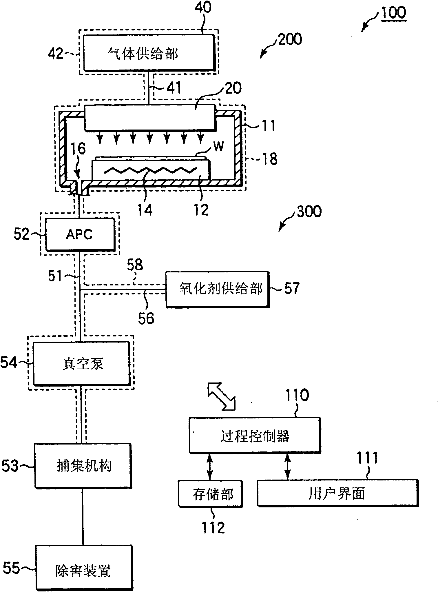
[0051] figure 2 It is a schematic diagram showing a film forming apparatus having an exhaust system configuration according to a second embodiment of the present invention. In this second embodiment, the arrangement position of the vacuum pump 54 is different from that of the first embodiment, and is located in the H 2 Between the supply position of O and the catch mechanism 53. Therefore, when H is supplied from the oxidant supply unit 57 to the exhaust pipe 51 through the pipe 56 2 After O, it reaches the trapping mechanism 53 after passing through the vacuum pump 54, so the exhaust gas and the H as the oxidant 2 O is fully mixed in the vacuum pump 54 and recovered by the trapping mechanism 53 after complete reaction. In this regard, in the first embodiment described above, H 2 The pressure of the supply position of O to the exhaust pipe 51 is low, and the exhaust gas is mixed with H in the exhaust pipe 51 2 O is captured by the capture mechanism 53 immediately after m...


PUM


Abstract

The invention provides an exhaust system structure of a film forming apparatus, a film forming apparatus and a method of disposing of exhaust gas. The exhaust system structure of film forming apparatus, comprising an exhaust pipe (51) for discharge of exhaust gas from a treatment vessel (11); an automatic pressure controller (52) provided at the portion of the exhaust pipe (51) near the treatment vessel (11); a vacuum pump (54) provided on the side of the exhaust pipe (51) downstream of the automatic pressure controller (52); an oxidizer supply section (57) for supplying an oxidizer at the location of the exhaust pipe (51) downstream of the automatic pressure controller (52); trap means (53) for recovery of products resulting from reactions of organometallic raw gas components and by-products contained in the exhaust gas with the oxidizer, provided on the side of the exhaust pipe (51) downstream of the oxidizer supply location; and a detoxifier (55) provided on the side of the exhaust pipe (51) downstream of the trap means (53).

Description

technical field [0001] The present invention relates to an exhaust system structure of a film forming apparatus for forming a predetermined film by CVD using an organometallic raw material, a film forming apparatus having such an exhaust system structure, and a method for treating exhaust gas. Background technique [0002] In the manufacturing process of a semiconductor device, various treatments such as film formation treatment, modification treatment, oxidation diffusion treatment, and etching treatment are performed on a semiconductor wafer as a substrate to be processed. [0003] Among them, a CVD (Chemical Vapor Deposition, chemical vapor deposition) method is often used as a film forming process. In this method, a predetermined process gas is introduced into a chamber containing a semiconductor wafer, and a predetermined film is formed by chemical reaction. In the CVD method, a process gas is reacted to form a film on a semiconductor wafer as a substrate to be processe...

Claims


Application Information

Patent Timeline
Patent Type & Authority Applications(China)
IPC IPC(8): C23C16/44H01L21/205H01L21/285H01L21/3205H01L23/52H01L21/28
CPCC23C16/4412H01L21/76873H01L21/28556Y02C20/30Y02P70/50C23C16/18C23C16/45561C23C16/45563
Inventor 松本贤治
Owner TOKYO ELECTRON LTD
Why Eureka
Try Eureka