
In-mould decorating injection moulding method and mould

A technology of injection molding and in-mold decoration, which is applied in the direction of metal processing, etc., can solve the problems affecting the application of IMD parts, high requirements for punching process, and difficult mold processing, so as to simplify the molding process of in-mold decoration, reduce energy consumption and Process time and the effect of reducing product defect rate

Inactive Publication Date: 2010-08-18
崔海徽
View PDF4 Cites 25 Cited by
  • Summary
  • Abstract
  • Description
  • Claims
  • Application Information

AI Technical Summary

Problems solved by technology

[0008] However, the problem with the current existing process is that the realization of the IMD process requires three steps, namely vacuum or high pressure forming, punching and in-mold injection molding.
It requires three pairs of molds and three types of equipment, which requires a large investment in equipment and molds, complex process flow, complex dimensional coupling relationship between the three-step processes, poor process reliability, low pass rate, slow production cycle, energy consumption and manpower. Large investment
[0009] There are three problems in the existing process: 1. In the process of vacuum forming or high pressure forming, the film is easy to rebound after film forming, so that the film cannot completely fit the die-cutting mold, so that the die-cutting process destroys the boundary of the film
[0010] 2. After the film is baked and cooled at high temperature, shrinkage and deformation will occur after the film is formed, resulting in the deviation of the shape and surface size of the formed film
3. High requirements for punching and cutting process
The die-cut film must match the shape and size of the injection mold, and the error range must be small. If the die-cut film is too large, it cannot be placed in the mold. If the die-cut film is too small, it must be injected during injection molding. Plastic can penetrate the surface of the film, making injection molded parts unusable
4. It is difficult to accurately position the film in the injection mold after punching, and the positioning deviation will lead to deviation of the decorative surface boundary of the product or the penetration of the injection molding melt into the decorative surface
5. Mold processing is difficult
The three processes require three different molds and three different equipment, and the cost is relatively high
Moreover, due to the size and shape-surface coupling relationship among the three processes, the three molds used in the three processes must be precisely matched, and repeated matching and debugging are required during mold development, resulting in a long processing cycle.
6. The thickness of the film is required to be high. Using the traditional IMD method, due to the large stretching depth of the film under high-pressure stamping, in order to ensure that the film is not damaged, the film thickness is about 3mm to 5mm. It is difficult for a film less than 3mm to be processed in IMD. method used in
In this case, the IMD process is often limited, which affects the application of IMD parts in the automotive industry

Method used


Image

  • In-mould decorating injection moulding method and mould
  • In-mould decorating injection moulding method and mould
  • In-mould decorating injection moulding method and mould

Examples


Embodiment Construction

[0040] The present invention is described in detail below in conjunction with accompanying drawing:

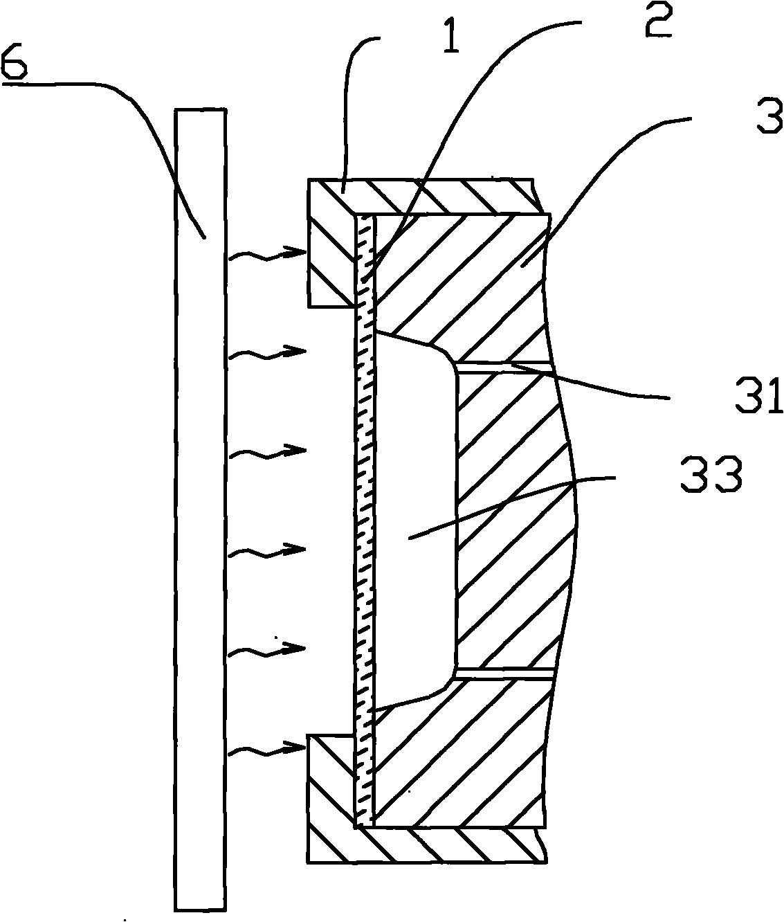
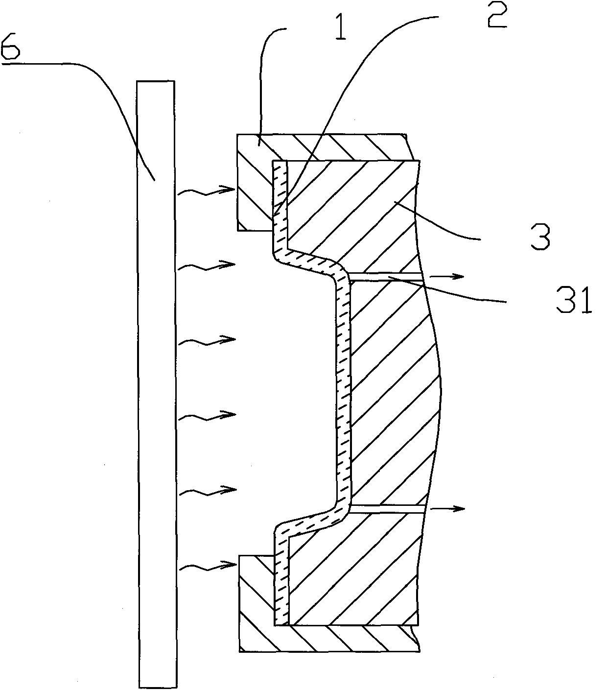
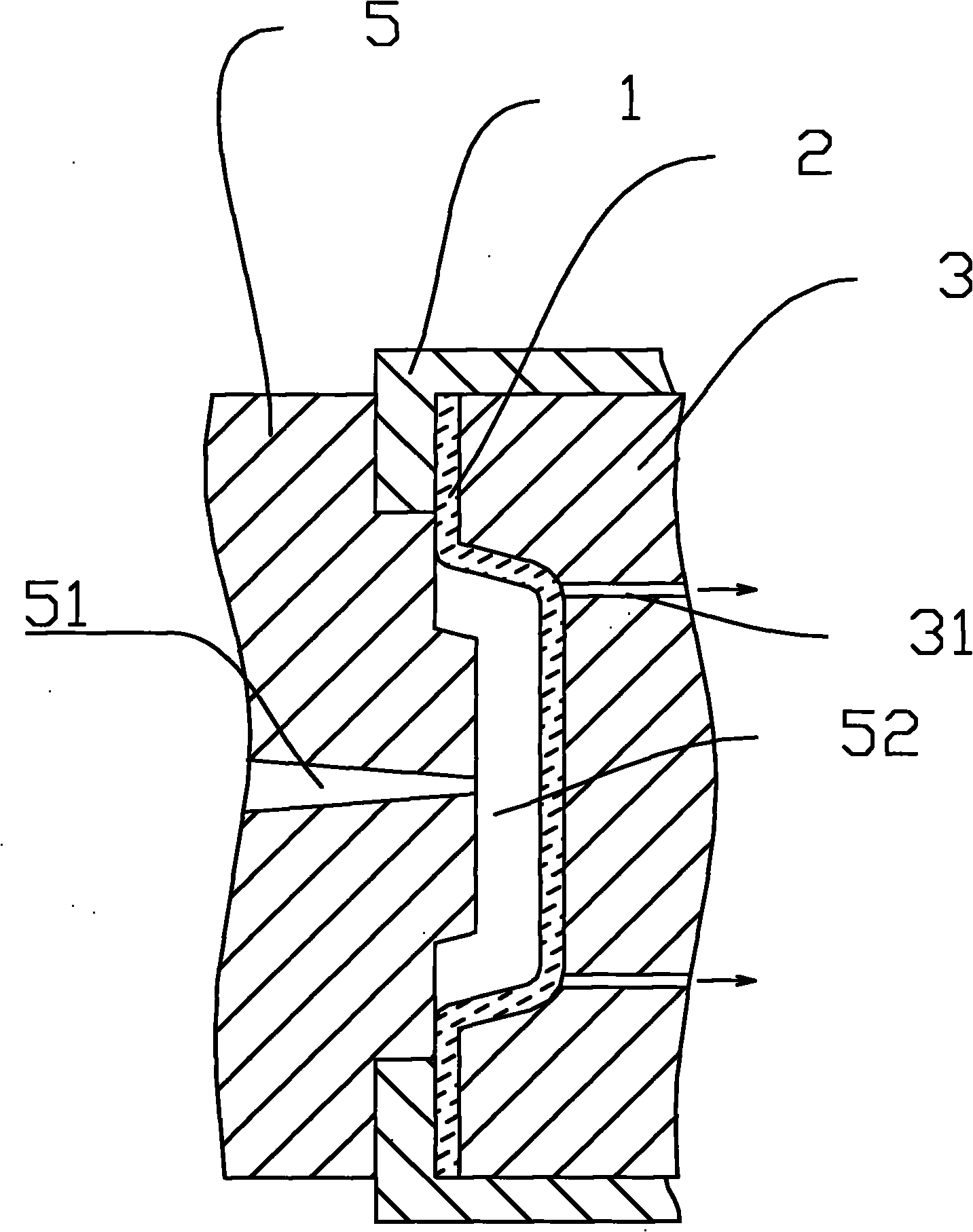
[0041] Such as figure 1 , figure 2 , image 3 and Figure 4 Shown, the injection mold used among the present invention comprises die 3, and it has a cavity 33 (not shown in the figure); out) Unicom, and the other end communicates with the cavity 33 between the film 2 and the die 3. The die 3 is provided with a film press frame 1 for pressing the edge of the film 2 .

[0042] The vacuum pumping device can use a vacuum pump in the prior art, and also can use other equipment with the same function.

[0043] The convex mold 5 is movably installed, and the convex mold 5 can be far away from or close to the concave mold 3 . The punch 5 is provided with an injection gate 51 . After the punch 5 and the die 3 are closed, there is an injection molding cavity 52 between the punch 5 and the film 2 .

[0044] The heating plate 6 can generate heat and is set movably. The heating p...


PUM

PropertyMeasurementUnit
thicknessaaaaaaaaaa

Abstract

The invention discloses an in-mould decorating injection moulding method, which is characterized by comprising the following steps: A, providing a thin film to cover the cavity of a female die; B, heating the thin film; C, sucking the air between the thin film and the female die so as to attach the thin film to the inner surface of the cavity; D, closing a male die and the female die to keep a die cavity between the male die and the thin film; and E, injecting an injection material into the die cavity and opening the mould after the injection material is shaped. The method can greatly simplify the in-mould decorating shaping process, complete the in-mould decorating process with a normal injection mould, save the pre-shaping and punching processes of the thin film and corresponding moulds, ensure easy development of the mould and reduce the investment in the mould and the equipment. The method is characterized by simplified production process, reduced rate of unqualified products, improved boundary appearance of parts, high production efficiency, low energy consumption and short process time. The method has low requirements on the thickness of the thin film; and the method of the invention can produce the in-mould decorating injection moulded part by using the thin films of 1 to 2mm so as to reduce the production cost.

Description

technical field [0001] The invention relates to an injection molding method for in-mold decoration and a mold for in-mold decoration injection molding. Background technique [0002] In-Moulding Decoration (IMD) is currently mostly used in the production of mobile phones, notebook computers and automotive interior parts. Usually need to pay more molds and multiple processes. Usually this process includes the following steps: [0003] a, providing a vacuum formable or high pressure formable film; [0004] b, with decorative patterns printed on the film; [0005] c. The film is evenly heated under tension, and then the softened film is made into a shell that matches the shape of the part through a vacuum forming mold or a high pressure forming mold; [0006] d, place the completed film shell of c in the trimming mold to complete the die-cutting of the redundant film boundary. [0007] e, providing an injection mold suitable for the IMD process, placing the film shell compl...

Claims


Application Information

Patent Timeline
Patent Type & Authority Applications(China)
IPC IPC(8): B29C45/14B29C45/76B29C45/26B26F1/44
Inventor 崔海徽王颂跃
Owner 崔海徽
Learn More