
Tera-hertz two-dimensional area array scanning imaging method and imaging system for implementing same

A technology of scanning imaging and imaging system, which can be used in measurement devices, material analysis by optical means, instruments, etc., and can solve the problems of long imaging time and so on.

Inactive Publication Date: 2010-08-18
HARBIN INST OF TECH
View PDF6 Cites 24 Cited by
  • Summary
  • Abstract
  • Description
  • Claims
  • Application Information

AI Technical Summary

Problems solved by technology

[0005] In order to solve the problem that the point-by-point scanning imaging of the prior art can only process a single data point and the imaging time is too long, and the area scanning imaging of the prior art can only quickly image small objects, a new method is proposed. Hertz two-dimensional area array scanning imaging method and imaging system for realizing the method

Method used


Image

  • Tera-hertz two-dimensional area array scanning imaging method and imaging system for implementing same
  • Tera-hertz two-dimensional area array scanning imaging method and imaging system for implementing same
  • Tera-hertz two-dimensional area array scanning imaging method and imaging system for implementing same

Examples


specific Embodiment approach 1

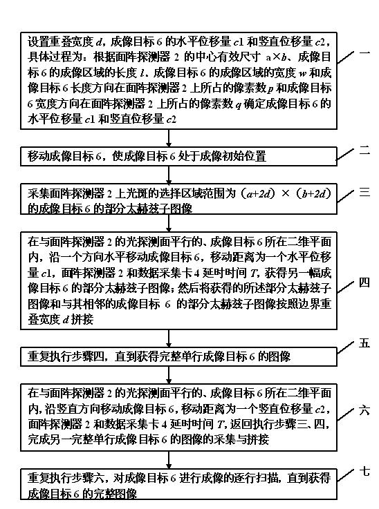
[0018] Specific implementation mode one, combine image 3 Describe this embodiment, the terahertz two-dimensional area array scanning imaging method, the specific process is as follows:

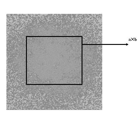
[0019] Step 1. Set the overlap width d , the horizontal displacement of imaging target 6 c 1 and the vertical displacement c 2. The specific process is: according to the effective range of the center of the area array detector 2 a x b , the length of the imaging region of the imaging target 6 l、 Width of the imaging area of ​​the imaging target 6 w and the number of pixels occupied by the length direction of the imaging target 6 on the area array detector 2 p and the number of pixels occupied by the width direction of the imaging target 6 on the area array detector 2 q Determine the horizontal displacement of the imaging target 6 c 1 and the vertical displacement c 2;

[0020] Step 2, moving the imaging target 6 so that the imaging target 6 is at the initial imaging position;

[...

specific Embodiment approach 2

[0033] Specific implementation mode two, This embodiment is a further description of step 1 in specific embodiment 1. The horizontal displacement amount described in step 1 c 1 and the vertical displacement c 2 are:

[0034] Horizontal displacement of imaging target 6 c 1= a x l / p , the vertical displacement of imaging target 6 c 2= b x w / q .

specific Embodiment approach 3

[0035] Specific implementation mode three, In this embodiment, the effective range of the center of the area array detector 2 in the first or second embodiment a x b Instructions, the effective range of the center of the area array detector 2 a=b .


PUM


Abstract

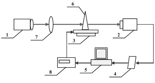
The invention discloses a tera-hertz two-dimensional area array scanning imaging method and an imaging system for implementing the same, which relate to a tera-hertz scanning imaging method and an imaging system. The method and the system solve the problem of overlong imaging time caused by the point-by-point scanning imaging which can only process single data points in the prior art and the problem that the area array canning imaging can only image small objects in the prior art. The method comprises the following steps of: scanning and imaging a two-dimensional area array by using a tera-hertz laser, an optical system, an area array detector, a two-dimensional translation stage, a stepper motor controller, a data acquisition card and a computer; under the condition that an imaging light source is fixed, moving the a two-dimension translation stage to a proper initial position and completely scanning a target in an imaging process, wherein a certain area of the imaging object is imaged at each time, and all sub-graphs are stitched together finally. An image of the imaging target is obtained by controlling the two-dimensional translation stage and the data acquisition card and processing and storing data. The method and the system are suitable for large-size and high-speed target imaging.

Description

technical field [0001] The invention relates to the field of laser imaging control, in particular to a terahertz scanning imaging method and system. Background technique [0002] Terahertz radiation (Terahertz, THz for short) usually refers to electromagnetic radiation with a frequency in the range of 0.1-10THz, which can penetrate most non-metallic non-polar substances, such as paper, envelopes, backpacks, etc., while having a lower photon Energy that does not cause harmful ionization and damage to living organisms like X-rays. Therefore, terahertz radiation imaging has great application prospects in medical inspection, safety inspection and food monitoring. [0003] Using a terahertz radiation source, a unit detector, a two-dimensional translation stage, a data acquisition card and a computer can scan and image the target point by point, and the imaging accuracy is high, but it is limited by the size of the detector, the scanning step size and the operating speed of the s...

Claims


Application Information

Patent Timeline
IPC IPC(8): G01N21/84G01V8/10
Inventor 李琦姚睿丁胜晖王骐
Owner HARBIN INST OF TECH
Learn More