Online fault diagnostic apparatus for circuit board

A fault diagnosis instrument and fault diagnosis technology, which is applied in the direction of electronic circuit testing, etc., can solve the problem of the diversity of the number and types of objects to be measured that cannot adapt to the diversity of the measured signal, the diversity of the excitation signal, and the inability to realize portable applications and independent interfaces To solve the problems of high price, achieve the effect of good open architecture, complete functions, high degree of automation and intelligence

Inactive Publication Date: 2010-08-18
ORDNANCE TECH RES INST OF THE GENERAL ARMAMENT DEPT PLA
View PDF4 Cites 41 Cited by
  • Summary
  • Abstract
  • Description
  • Claims
  • Application Information

AI Technical Summary

Problems solved by technology

Among them, PCI and ISA are the internal buses of the computer. The ISA bus appeared earlier and is no longer used. The PCI bus is faster, but it can only be used in desktop computers and cannot meet the requirements of portability; the IEEE488.2 bus belongs to independent instrument control. bus, but the price of independent instruments with its interface is relatively high, it cannot be used in portable applications, and is not suitable for popularization and use; fault diagnosis instruments based on VXI, PXI and CompactPCI buses are a set of completely independent test systems based on computers and industrial computers. There is an independent chassis with good performance, but VXI is suitable for large-scale general-purpose test projects, with high cost and poor portability
The structure of PXI and CompactPCI is small, but the design of the bus cannot be changed, and it cannot adapt to the diversity of the measured signals, the diversity of the number and types of the measured objects, and the diversity of the excitation signals, so it is not suitable for practical use.

Method used


Image

  • Online fault diagnostic apparatus for circuit board
  • Online fault diagnostic apparatus for circuit board
  • Online fault diagnostic apparatus for circuit board

Examples


Embodiment Construction

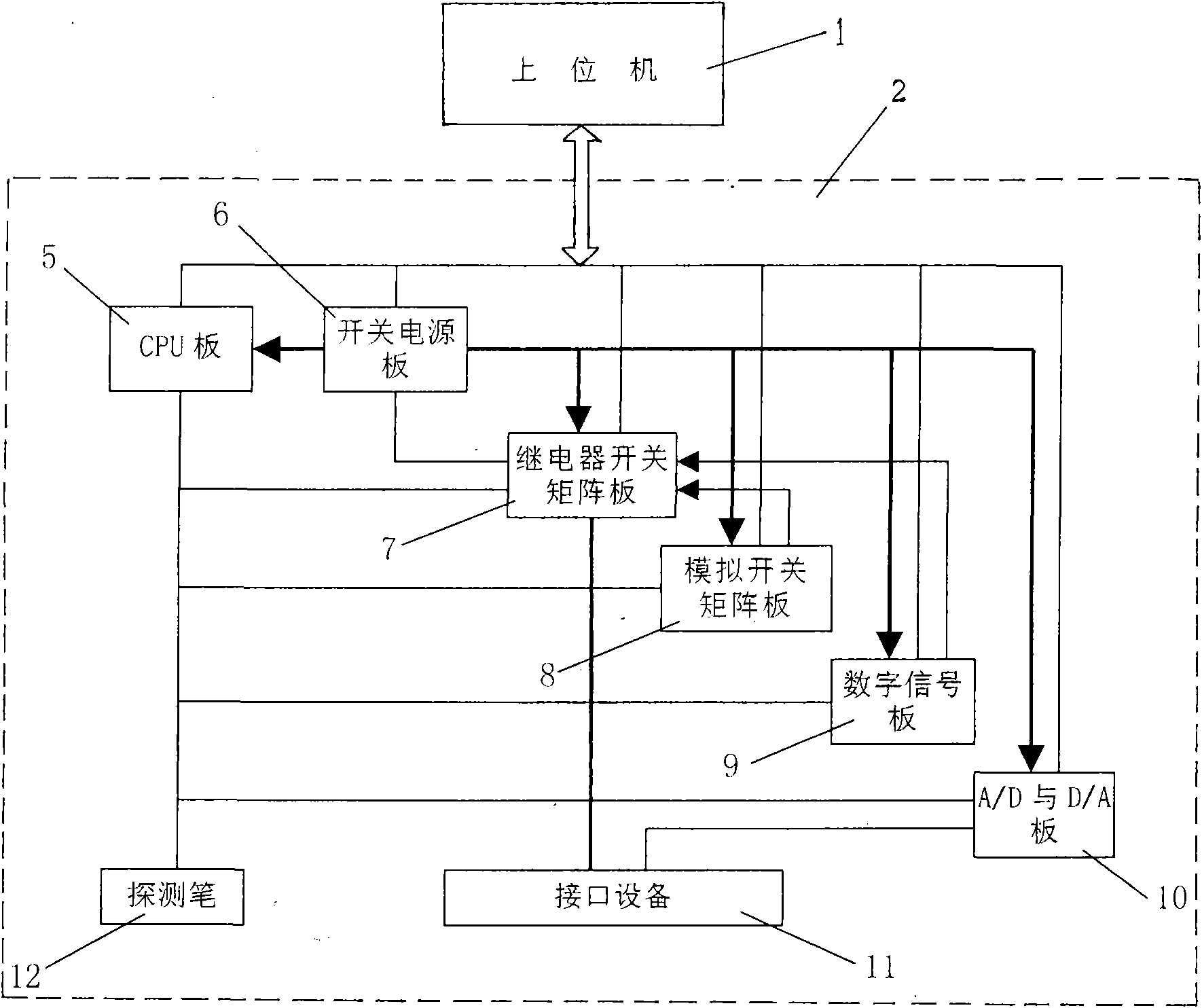
[0025] Such as figure 1 As shown, the present invention includes two parts, an upper computer 1 and a lower computer 2, wherein the upper computer 1 adopts a portable notebook computer with built-in fault diagnosis expert system software. The upper computer 1 is a platform for human-computer interaction, and its functions mainly include the generation control of excitation signals, test data collection, analysis and reasoning, etc., combined with the fault diagnosis expert system for fault diagnosis of circuit boards or components. After the tested circuit board is connected to the interface device of the lower computer, the upper computer 1 controls the lower computer 2 to apply various excitation signals to the tested circuit board, and then collects the response signals; according to the collection results, the fault diagnosis expert system is started , locate the fault to a replaceable component.

[0026] The lower computer 2 includes a CPU board 5, a switching power supp...


PUM


Abstract

The invention relates to an online fault diagnostic apparatus for a circuit board. The online fault diagnostic apparatus comprises an upper computer and a lower computer, wherein the upper computer is used for performing online signal processing and fault diagnosis, the lower computer is used for providing needed signals for a tested circuit board and uploading test information, and the upper computer and the lower computer are connected and communicated by using a serial bus. The lower computer comprises a CPU (Central Processing Unit) board, a switching power board, a relay switch matrix board, an analog switch matrix board, a digital signal board, A/D (Analog to Digital) and D/A (Digital to Analog) boards, an interface device and a detector, wherein all functional circuit boards are mutually connected in the manner of a system bus, the interface device, the relay switch matrix board and the A/D and D/A boards are electrically connected, and the detector and the CPU board are electrically connected. The invention has strong universality, flexible assembly, simple operation and high fault diagnosis ratio and is suitable for the online fault diagnosis and location of the circuit boards in various industries.

Description

technical field [0001] The invention relates to an electronic detection device, in particular to an online fault diagnosis instrument for circuit boards. Background technique [0002] As an important part of complex equipment, electronic equipment has the characteristics of complex system, high technical content, and high failure rate. Once the electronic equipment fails, it will greatly affect the normal operation of the entire equipment. It is of great significance to quickly and accurately locate the fault of the circuit board, and then repair it in time. [0003] The development of circuit board fault diagnosis equipment has a history of many years. At present, there are mainly two detection devices: an online fault diagnosis instrument for testing components one by one and a fault diagnosis instrument for testing circuit boards. The fault diagnosis instrument for detecting electronic components is based on post-drive technology, and uses fixtures to test all electronic...

Claims


Application Information

Patent Timeline
Patent Type & Authority Applications(China)
IPC IPC(8): G01R31/28
Inventor 刘耀周王振生刘焕照赵昉方兴桥张永鹏
Owner ORDNANCE TECH RES INST OF THE GENERAL ARMAMENT DEPT PLA
Why Eureka
Try Eureka