

Method for actuating a solenoid valve and associated device
A solenoid valve, current technology, applied in the direction of valve operation/release device, valve device, magnet, etc., can solve the problem of delaying the actual switching process of the solenoid valve, delaying the switching of the solenoid valve, unable to correct the delay, etc., to achieve a small injection volume, The effect of reducing electrical delay and shortening delay time
Inactive Publication Date: 2010-08-18
CONTINENTAL AUTOMOTIVE GMBH
View PDF4 Cites 20 Cited by
- Summary
- Abstract
- Description
- Claims
- Application Information
AI Technical Summary
Problems solved by technology
The problem with this usual actuation is that, due to the inductance of the magnetic coil, the actuating current is maintained for a certain time interval after the moment of switching off, thus delaying the actual switching process of the solenoid valve (Schaltvorgang)
Furthermore, in conventional injectors there is the problem that eddy currents are induced in the magnetic coil after the switch-off moment due to the rapid change of the actuating current, which counteract the cancellation of the magnetic field, which in turn delays the switching of the solenoid valve (Schalten)
This electrical delay due to eddy currents is particularly problematic when very small injection quantities and thus very short solenoid valve opening times are desired, since the aforementioned delay cannot be corrected
Method used
View moreImage
Smart ImageViewing Examples


Examples
Embodiment Construction
Login to View More PUM
 Abstract
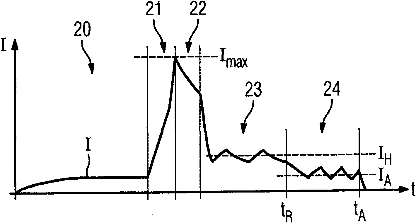
The invention relates to a method for actuating a solenoid valve (4) for generating precise opening and closing times of the solenoid valve (4). To this end, an actuating current (I) provided for actuating the solenoid valve (4) and applied to an actuating coil (5) of the solenoid valve (4) is already reducing in a reduction phase (24) prior to a switch-off point in time (tA) of the solenoid valve (4) relative to a maintained level (IH) of the actuating current (I), at which the solenoid valve (4) is reliably held in an actuating position (16).
Description
technical field The invention relates to a method for actuating a solenoid valve for high-pressure injection in a motor vehicle. The invention also relates to a device for carrying out the method. Background technique Controlled solenoid valves are often used to inject fuel directly into the motor vehicle engine. A defined (ie neither too little nor too much) injection quantity is thus desired, which can be achieved by precisely controlling the opening and closing times of the solenoid valves. Solenoid valves are usually actuated via a solenoid coil loaded with an actuating current. Typically, a yoke in the magnet coil is magnetized by the induced magnetic field. The actuating element acting as an armature is moved by the generated magnetic force against the spring force toward the yoke into the actuating position. In current actuation methods, the actuation current is generally controlled in such a way that the actuation current is increased in the precharging phase t...
Claims
Login to View More Application Information
Patent Timeline
 Patent Type & AuthorityApplications(China)
IPC IPC(8): F02D41/20F02D41/40
CPCF02D41/40H01F7/1805F16K31/0675F02D2041/2058F02D41/20Y10T137/0318
InventorC·哈根米勒A·迈耶-迪克
OwnerCONTINENTAL AUTOMOTIVE GMBH