Accumulator

A technology of accumulator and oil channel, which is applied in the direction of accumulator device, actuator accumulator, fluid pressure actuating device, etc., can solve the problem that the expansion and contraction stroke of the bellows cannot be ensured, and can prevent abnormal deformation and improve durability. sexual effect

Active Publication Date: 2010-08-18
EAGLE INDS
View PDF10 Cites 14 Cited by
  • Summary
  • Abstract
  • Description
  • Claims
  • Application Information

AI Technical Summary

Problems solved by technology

[0013] (ハ) When the zero falls, the bellows shrinks when the auxiliary bellows is extended, and the bellows stop shrinking when the auxiliary piston reaches the bottom, so a sufficient bellows telescopic stroke cannot be ensured

Method used


Image

  • Accumulator
  • Accumulator
  • Accumulator

Examples


Embodiment

[0096] Embodiments of the present invention will be described below with reference to the drawings.

no. 1 example

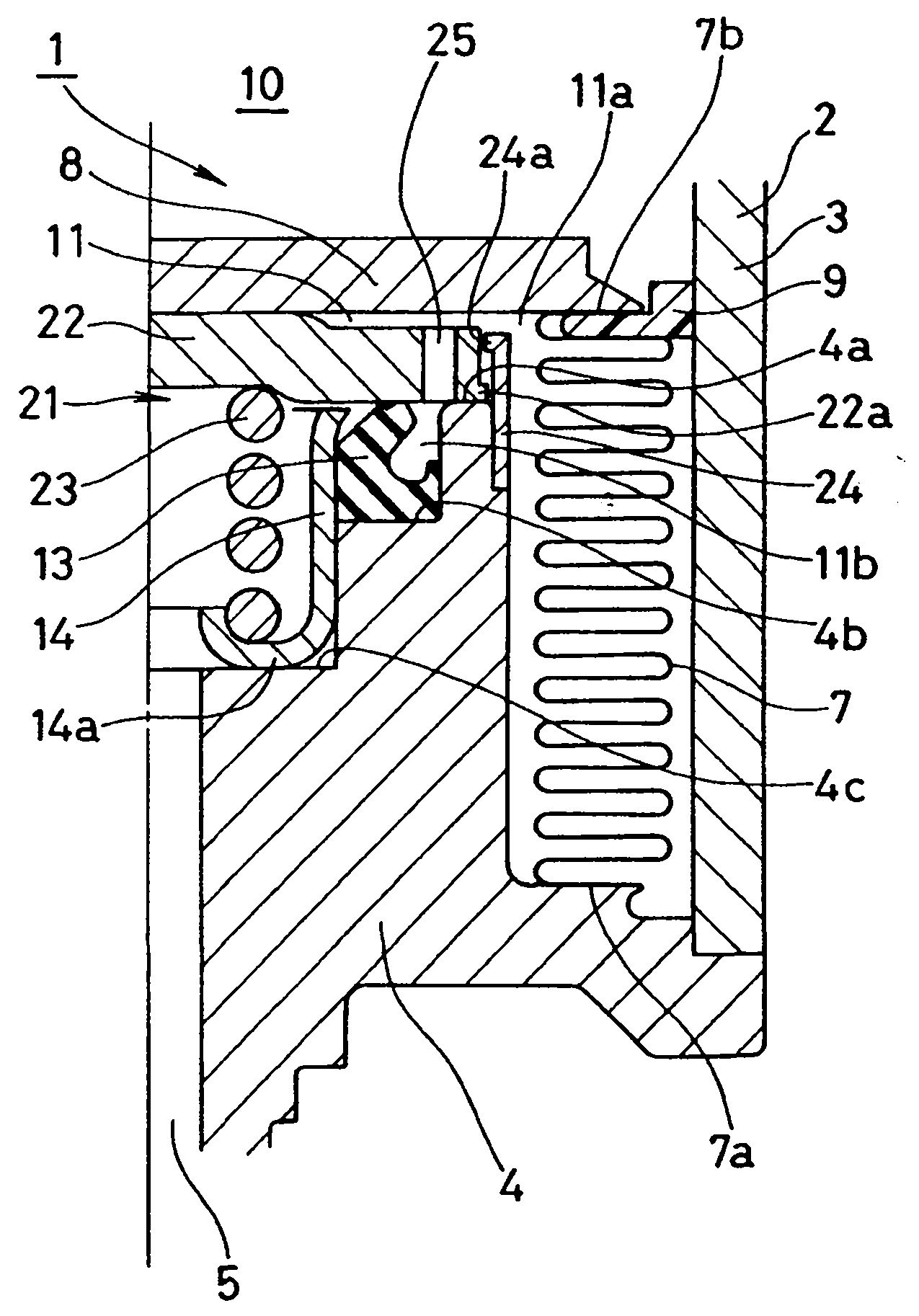
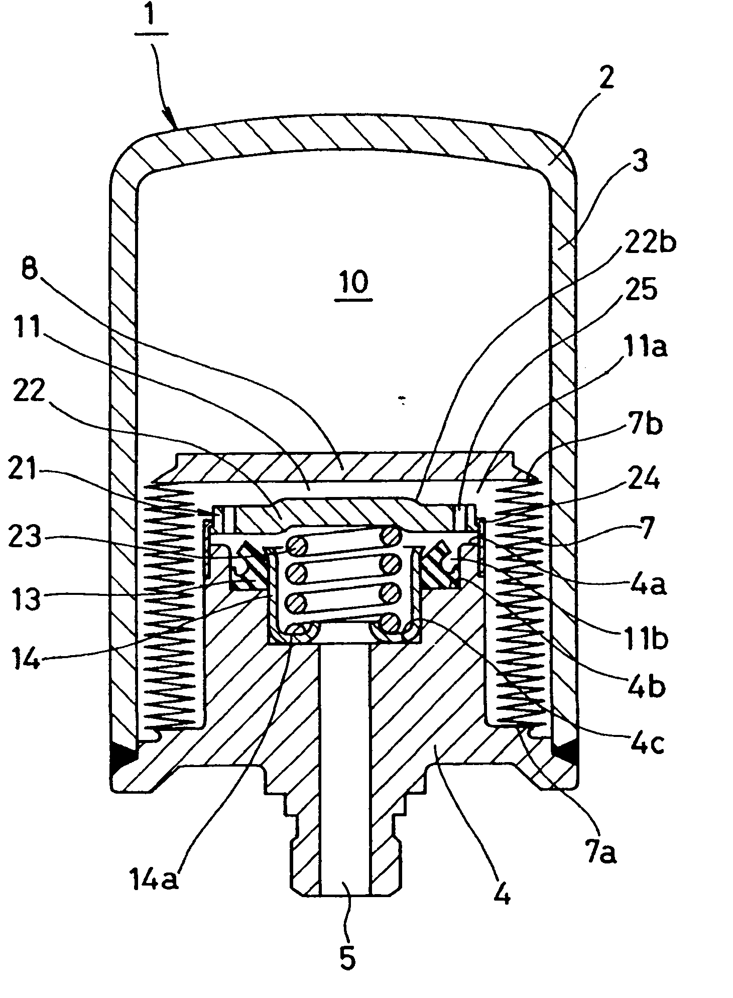
[0098] 1 to 3 show a full section and a partial section of an energy store 1 according to a first embodiment of the invention. Figure 1, Figure 2, and Figure 3 show the states during normal operation, zero drop, and thermal expansion in the zero drop state, respectively.

[0099] The accumulator 1 of the present embodiment is a metal bellows type accumulator using a metal bellows as the bellows 7, and is configured as follows.

[0100] That is, first, an accumulator case 2 having an oil passage 4 connected to a pressure pipe (not shown) is provided, and a bellows 7 is arranged inside the case 2 to separate the inner space of the case 2 into a gas chamber in which high-pressure gas is enclosed. The chamber 10 communicates with the liquid chamber 11 of the passage hole 5 of the oil passage 4 . The casing 2 is formed by combining a bottomed cylindrical cover 3 and an oil passage 4 fixed to an opening at one end of the cover 3, but the proportion and structure of the parts of the...

no. 2 example

[0120] Although the accumulator 1 in the above-mentioned first embodiment is an external gas accumulator, its pressure difference adjustment mechanism 21 can also be applied to an internal gas accumulator. Fig. 4 shows an example thereof, the bellows cover 8 is installed on the fixed end 7a of the bellows 7 of the movable end 7b, and is fixed on the end cover 6 on the top of the shell 2, thereby constituting the inner peripheral side of the bellows 7 as the air chamber 10 and the outer peripheral side It is the inner gas accumulator 1 of the liquid chamber 11. The configuration and operation of the pressure difference adjusting mechanism 21 are the same as those of the first embodiment, so the same reference numerals are given and descriptions thereof are omitted, but the difference is that the communication passage 25 is provided so that the standing portion (cylindrical portion) of the stopper 24 is horizontal. Porous.


PUM


Abstract

An outer gas type or inner gas type accumulator is provided with a mechanism for reducing a pressure difference generated when liquid and gas confined in a liquid chamber at the time of a zero-down state is expanded thermally. The mechanism reduces the pressure difference between the inside and outside of a bellows to suppress abnormal deformation of the bellows. A movable plate supported by spring means is provided on the bellows cap side of an oil port. In normal operation, the movable plate is supported by the spring means and separated from a seal. In a zero-down state, the movable plate is pushed by the bellows cap and makes contact with the seal while elastically deforming the spring means. When the liquid and gas confined in the liquid chamber in the zero-down state is expanded thermally, the bellows cap moves, with the movable plate being in contact with the seal, up to a position at which the liquid pressure and the gas pressure balance each other.

Description

technical field [0001] The present invention relates to an accumulator used as a pressure storage device or a pulse pressure attenuation device. The accumulator of the present invention is used, for example, in hydraulic lines and the like in vehicles such as automobiles. Background technique [0002] Previously, there has been known an accumulator in which bellows are arranged inside an accumulator housing having an oil passage connected to a pressure pipe, and the inner space of the housing is partitioned into an air chamber enclosing high-pressure gas In this accumulator, the liquid chamber communicated with the passage hole of the oil passage has the following type as its type: As shown in FIG. The other end (fixed end) 51b is fixed to the end cap 54 on the top of the casing 53, the inner peripheral side of the bellows 51 becomes the air chamber 55, and the outer peripheral side becomes the liquid chamber 56 (because the air chamber 55 is set on the inner peripheral sid...

Claims


Application Information

Patent Timeline
Patent Type & Authority Applications(China)
IPC IPC(8): F15B1/08
CPCF15B2201/3153F15B2201/205F15B2201/411F15B1/103
Inventor 中冈真哉三宅邦明中山纯一山田泰辅渡边健斋藤知成
Owner EAGLE INDS
Why Eureka
Try Eureka