Valve for controlling a gas flow, liquid separator, ventilation system and internal combustion engine comprising such a valve

A liquid separation and separator technology, applied in the field of air flow valves, can solve the problems of inability to provide scalability, difficult sealing, difficult engine adaptation, etc., and achieve the effects of small space requirements, low cost, and a small number of parts

Inactive Publication Date: 2012-12-12
REINZ DICHTUNGS
View PDF10 Cites 12 Cited by
  • Summary
  • Abstract
  • Description
  • Claims
  • Application Information

AI Technical Summary

Problems solved by technology

[0010] The disadvantage of this prior art is that such valves can only be sealed with difficulty and are difficult to adapt to various types of engines
It also does not provide easy scalability

Method used


Image

  • Valve for controlling a gas flow, liquid separator, ventilation system and internal combustion engine comprising such a valve
  • Valve for controlling a gas flow, liquid separator, ventilation system and internal combustion engine comprising such a valve
  • Valve for controlling a gas flow, liquid separator, ventilation system and internal combustion engine comprising such a valve

Examples


Embodiment Construction

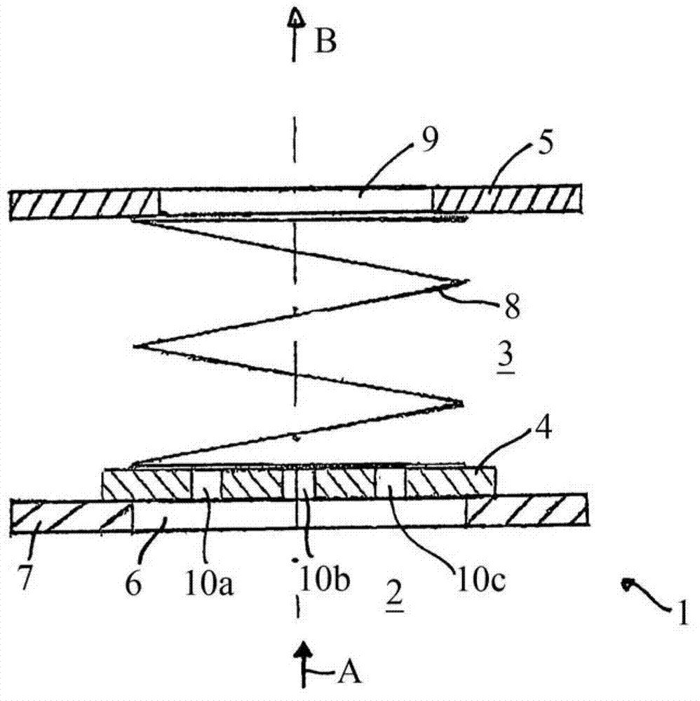
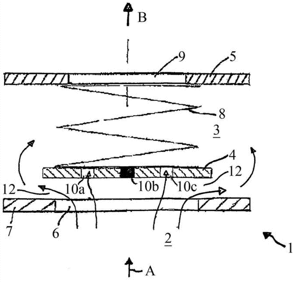
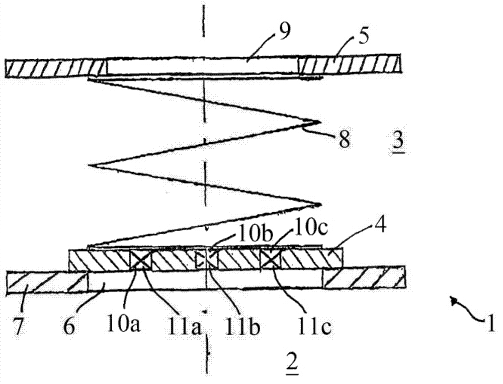
[0040] Figure 1a A valve 1 is shown, which includes a base plate or valve seat 7. The valve seat 7 includes a valve port 6. If the pressure difference between the pressure side 2 and the suction side 3 of the valve 1 is given, the valve port gas can flow through the valve port 6 from the first pressure side 2 of the valve to the valve The second suction side 3. If necessary, the valve port 6 is closed by the valve disc 4. The valve disc 4 is located on the valve seat 7. In FIG. 1, the valve disc is supported by an elastic coil spring 8 on the valve support 5, which includes a gas passage opening 9. The disc spring 8 as a compression spring is used to preload the valve disc in the direction opposite to the valve port, so that the valve disc 4 only detaches upward after exceeding a certain pressure difference between the pressure side 2 and the suction side 3 The valve seat 7 and the valve port 6 are opened. It is also possible to install the spring without preloading, so th...


PUM


Abstract

The invention relates to a valve for controlling a gas flow, as it is used, for example, for controlling the gas flow between a crankcase and an intake tract of an internal combustion engine. The invention further relates to a liquid separator and to a ventilation system for the above-mentioned exemplary use for a crankcase and to an internal combustion engine.

Description

Technical field [0001] The present invention relates to a valve for controlling air flow, such as a valve for controlling air flow between a crankcase and a suction pipe of an internal combustion engine. The valve of the present invention also relates to a liquid separator and ventilation system for the above-mentioned exemplary applications to crankcases and internal combustion engines. Background technique [0002] For example, the present invention is used to eliminate oil mist and / or oil droplets from blow-by gas of an internal combustion engine. For this reason, the blow-by gas is usually guided from the crankcase to the intake pipe of the internal combustion engine through a ventilation duct belonging to the ventilation system, and in this way is recirculated to the combustion process. However, it is necessary to remove the oil previously stored in these leaks. The remaining oil can be carried away with the oil mist and / or oil droplets in the leak. [0003] Oil separation ...

Claims


Application Information

Patent Timeline
Patent Type & Authority Applications(China)
IPC IPC(8): F01M13/04F01M13/00F16K15/02F16K15/04F16K17/04F16K17/30B01D45/10B01D45/16G05D7/01F01M13/02
CPCF01M2013/0066F01M13/0011F16K17/30F01M2013/0427F01M2013/0044F16K17/044F01M2013/0438G05D7/0133F16K17/0493F01M2013/0055F01M13/04F16K17/0413F16K15/028F01M13/023F01M2013/0433
Inventor 弗朗西斯科・齐塔罗萨贝恩德・斯帕司
Owner REINZ DICHTUNGS
Why Eureka
Try Eureka