
Braking pedal feel simulating device of automobile brake-by-wire system

A brake pedal and simulation device technology, which is applied to brake transmission devices, mechanical brake transmission devices, brakes, etc., can solve the problems of excellent simulation effect and complex structure, and achieve good braking stability, large pedal stroke, The effect of simple structure

Inactive Publication Date: 2014-01-01
BEIHANG UNIV
View PDF6 Cites 11 Cited by
  • Summary
  • Abstract
  • Description
  • Claims
  • Application Information

AI Technical Summary

Problems solved by technology

The spring type simulation device has simple structure, low cost and reliable performance; the hydraulic type simulation device has a complex structure, but its simulation effect is better than that of the spring type; the active type simulation device has adjustable pedal characteristics and superior performance, but the structure is complex

Method used


Image

  • Braking pedal feel simulating device of automobile brake-by-wire system
  • Braking pedal feel simulating device of automobile brake-by-wire system
  • Braking pedal feel simulating device of automobile brake-by-wire system

Examples


Embodiment Construction

[0023] The present invention will be further described below in conjunction with the accompanying drawings and specific embodiments.

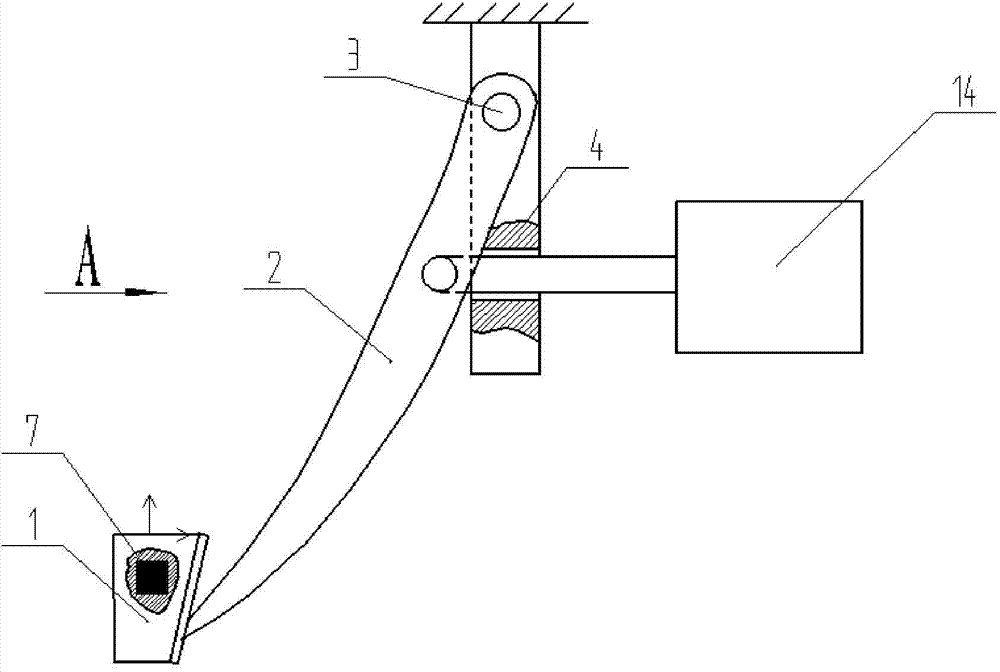
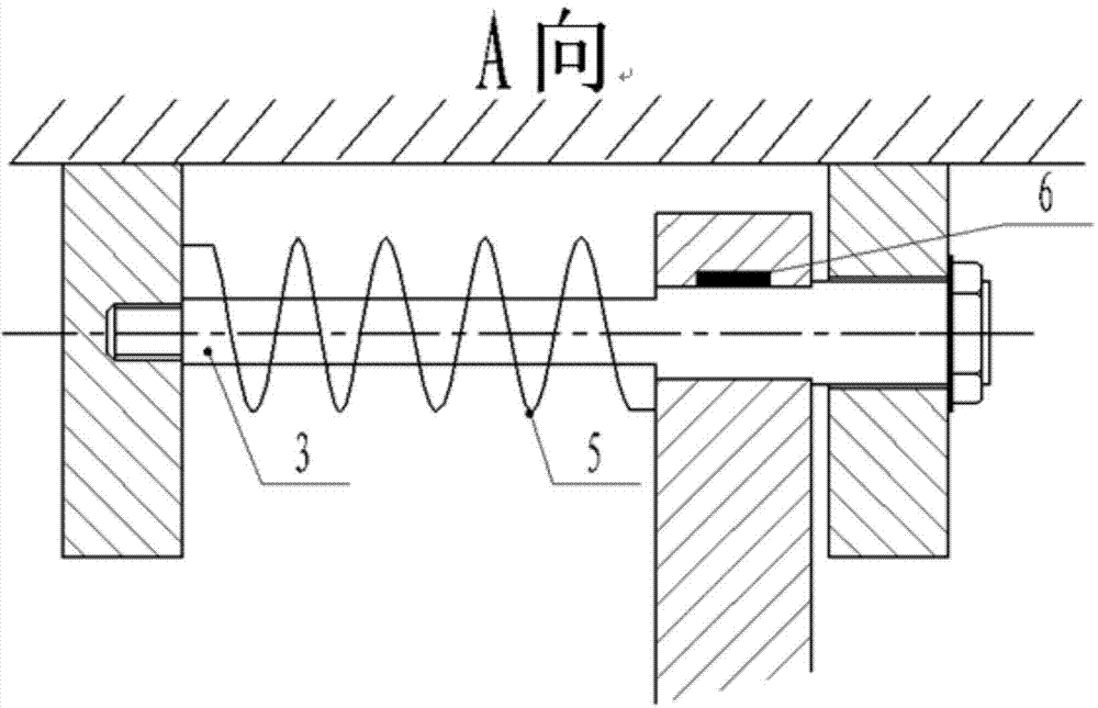
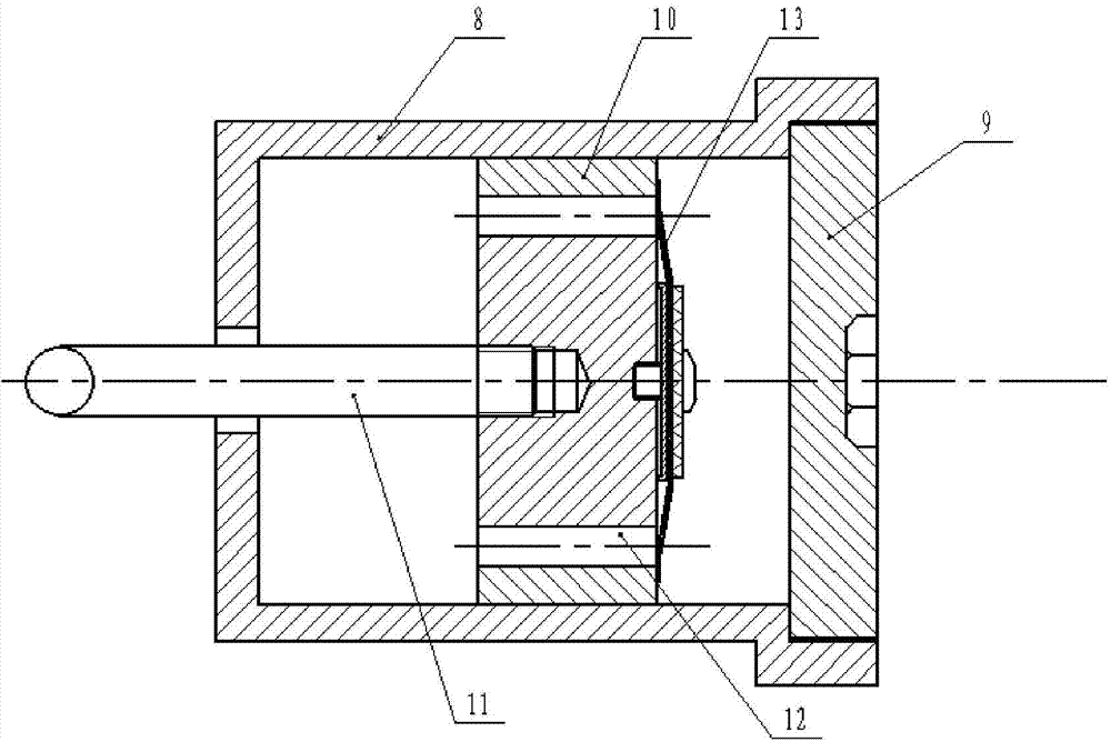
[0024] Such as Figure 1a Shown is a schematic diagram of the overall structure of the present invention. Brake-by-wire system brake pedal feeling simulation device includes a brake pedal 1, a pedal control arm 2, a pedal shaft 3, a pedal fixing bracket 4, a torsion spring 5, a pedal angular displacement sensor 6, a pedal force sensor 7 and a pedal feeling simulator 14. The position connection relationship between them is: the brake pedal 1 is fixedly connected with the pedal control arm 2; the upper end of the pedal control arm 2 is processed with a round hole, which is connected with the pedal shaft 3 in rotation; the pedal shaft 3 is fixedly installed on the pedal fixing bracket 4 In the mounting hole; the pedal fixing bracket 4 is provided with a guide hole, and the diameter of the guide hole is matched with the outer diameter of the push ...


PUM


Abstract

A braking pedal feel simulating device of an automobile brake-by-wire system comprises a braking pedal, a pedal controlling arm, a pedal shaft, a pedal fixing support, a torsion spring, a pedal angle displacement sensor, a pedal force sensor and a pedal feel simulator. The braking pedal is fixedly connected with the pedal controlling arm, a round hole is processed at the upper end of the pedal controlling arm which is rotatably connected with the pedal shaft, the pedal shaft is mounted in a mounting hole of the pedal fixing support, a guide small hole is formed in the pedal fixing support, the diameter of the guide small hole is in interference fit with the outer diameter of a pushing rod, the torsion spring is cylindrical and is sleeved on the pedal shaft in a hollow manner, one end of the torsion spring is fixedly connected on the pedal fixing support while the other end of the same is connected on the pedal controlling arm, the torsion spring reverses and generates spring force along with rotating of the pedal controlling arm, the pedal angle displacement sensor is mounted in the round hole at the upper end of the pedal controlling arm, the pedal force sensor is mounted on the braking pedal, and the front end of a pushing rod of the pedal feed simulator is rotatably connected with the pedal controlling arm.

Description

technical field [0001] The invention relates to a brake pedal simulation device of an automobile braking system, in particular to a brake pedal feeling simulation device of an automobile brake system by wire, and belongs to the technical field of automobile manufacturing. Background technique [0002] The control-by-wire technology is developed with the development of electronic technology and network technology. The electric vehicle brake-by-wire system is formed by combining the control-by-wire technology with the composite braking system of electric vehicles. The wire is the information transmission medium, and the electric drive element is used as the actuator. The control unit recognizes the driver's braking intention according to the pedal action information, distributes the braking force, and then controls the actuator to realize the braking of the electric vehicle. Pedal action information can be pedal displacement, speed or pedal force, etc. [0003] In the brake-b...

Claims


Application Information

Patent Timeline
Patent Type & Authority Applications(China)
IPC IPC(8): B60T11/04B60T13/22
Inventor 姬芬竹朱文博
Owner BEIHANG UNIV
Learn More