Booster-type gas compressor

A technology of compressor and compressed gas, applied in liquid variable capacity machinery, mechanical equipment, fluid parameters, etc., can solve problems such as large torque change, increased current, accelerated seal damage, etc.

Inactive Publication Date: 2007-07-18
ANEST IWATA CORP
View PDF0 Cites 11 Cited by
  • Summary
  • Abstract
  • Description
  • Claims
  • Application Information

AI Technical Summary

Problems solved by technology

Therefore, due to the pressure difference above and below the piston 36, the torque change in one rotation becomes larger, so that the electric current of the motor 34 directly mounted on the crankcase 29 increases, so that the outer peripheral surface of the piston 36, piston ring, Damage to drive shaft 30, bearings 41 and 42 of crankshaft 31 and seals of sliding parts

Method used


Image

  • Booster-type gas compressor
  • Booster-type gas compressor
  • Booster-type gas compressor

Examples


Embodiment Construction

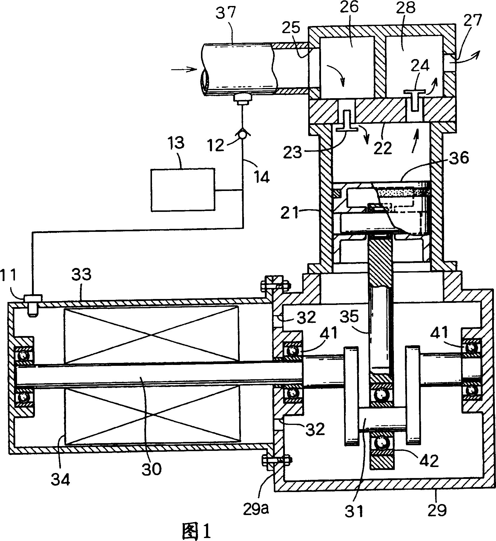
[0014] Fig. 1 shows a first embodiment of the booster type gas compressor of the present invention.

[0015] The basic structure of the supercharged gas compressor is not much different from that in FIG. 4 . The same reference numerals refer to the same components. Therefore, description thereof is omitted and only differences are described.

[0016] In FIG. 1 , there is no air hole 38 communicating with the outside air, and a compressed air introduction hole 11 is formed on the motor case 33 instead of the ventilation hole.

[0017] The compressed gas supply channel 37 is connected to the compressed gas introduction hole 11 through a bypass conduit 14 having a one-way valve 12 and a pressure regulator 13 which are closed in the direction toward the compressed gas supply channel 37 and closed in the opposite direction. open, the pressure regulator is, for example, a pressure regulating valve or a pressure reducing valve.

[0018] By opening a valve (not shown), compressed g...


PUM


Abstract

In a pressure-charged gas compressor, a crankshaft connecting integrally with a drive shaft is driven by a motor in a motor box. The crankshaft connects with a piston rod having a piston on an upper end and extending perpendicularly to the crankshaft, thereby, the piston moves vertically, as the crankshaft rotates. Compressed gas from a compressed gas flowing passage is supplied to a compression chamber disposed above the piston and is further compressed by the piston. The compressed gas flowing passage is connected with the motor box by a bypass pipe to maintain pressure in the motor box greater than atmospheric pressure.

Description

technical field [0001] The present invention relates to a pressurized gas compressor in which the compressed gas is further compressed by a reciprocating piston. Background technique [0002] As shown in FIG. 4 , a suction valve 23 is provided on one side of the top wall 22 of the cylinder 21 , and a discharge valve 24 is provided on the other side of the top wall 22 . Above the suction valve 23 and the discharge valve 24, a suction chamber 26 having an inlet 25 and a discharge chamber 28 having an outlet 27 are respectively formed. Below the cylinder 21 , a crankshaft 31 integrally formed with a drive shaft 30 is provided in a crankcase 29 . The drive shaft 30 is driven by a motor 34 in a motor box 33 mounted on the side wall 29a of the crankcase 29 so that gas can pass through. Using the piston rod 35, the piston 36 is moved up and down in the cylinder 21 by the crankshaft 31 formed with the drive shaft 30, so that the N introduced into the compression chamber above the ...

Claims


Application Information

Patent Timeline
Patent Type & Authority Applications(China)
IPC IPC(8): F04B35/04F04B39/00
CPCF04B39/123F04B35/04F04B39/121F04B39/128F04B49/022F04B2205/18F05B2210/12Y10S417/00
Inventor 井上弘
Owner ANEST IWATA CORP
Why Eureka
Try Eureka