Cap and ink-jet head protection assembly

Active Publication Date: 2008-11-20
BROTHER KOGYO KK
View PDF6 Cites 13 Cited by
  • Summary
  • Abstract
  • Description
  • Claims
  • Application Information

AI Technical Summary

Benefits of technology

[0009]One or more aspects of the present invention provide an improved cap that reduces pressure differences between ex

Problems solved by technology

This may cause an event that the transferred adhesive closes or otherwise restricts the flo

Method used


Image

  • Cap and ink-jet head protection assembly
  • Cap and ink-jet head protection assembly
  • Cap and ink-jet head protection assembly

Examples


first embodiment

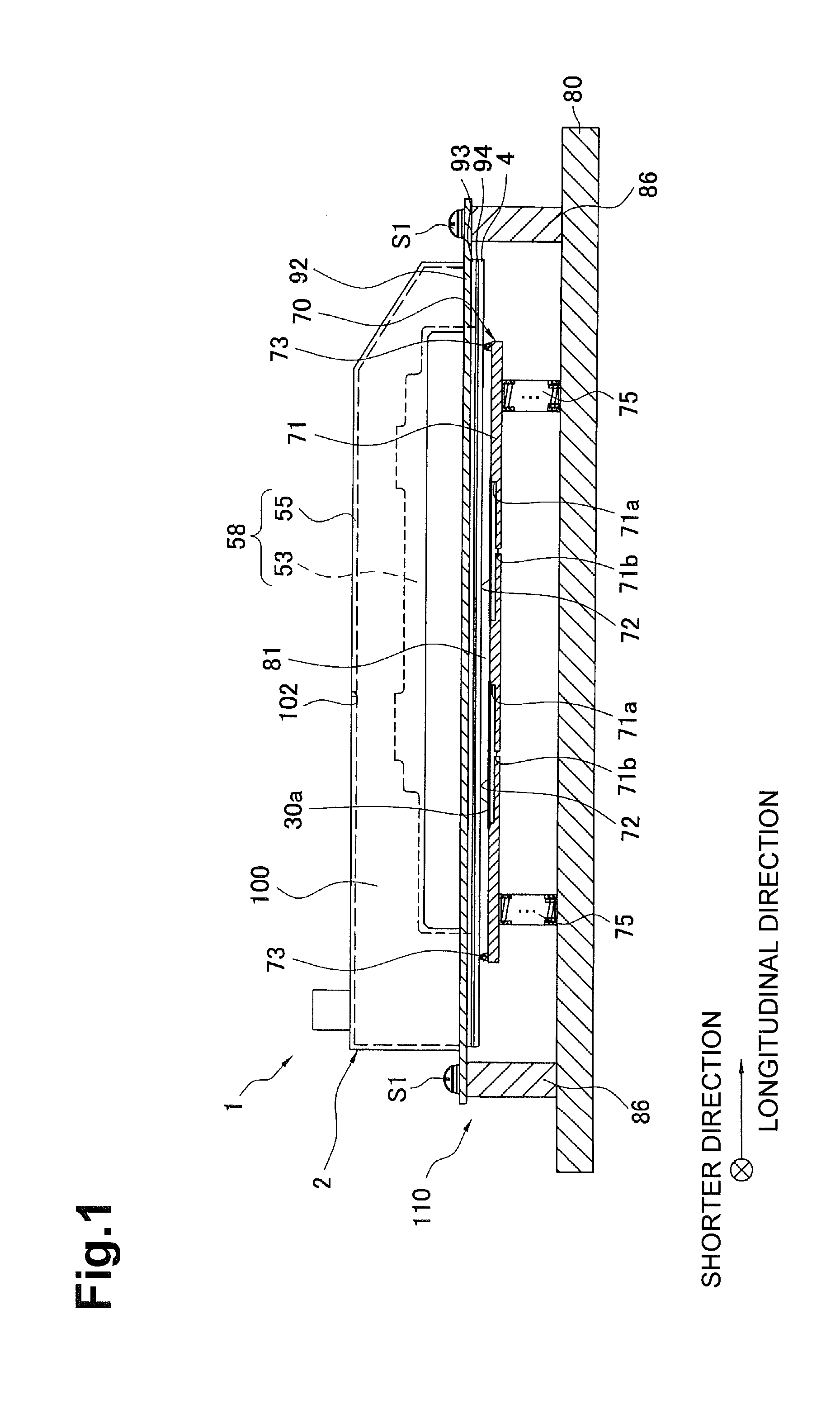
[0031]FIG. 1 schematically shows the configuration of an ink-jet head protection assembly according to the invention. As shown in FIG. 1, the ink-jet head protection assembly 1 is composed of an ink-jet head 2 and a cap unit 110 which covers an ink ejecting face 30a as the bottom surface of the ink-jet head 2. The ink-jet head 2 generally has a rectangular parallelepiped shape which is long in the right-left direction in FIG. 1.

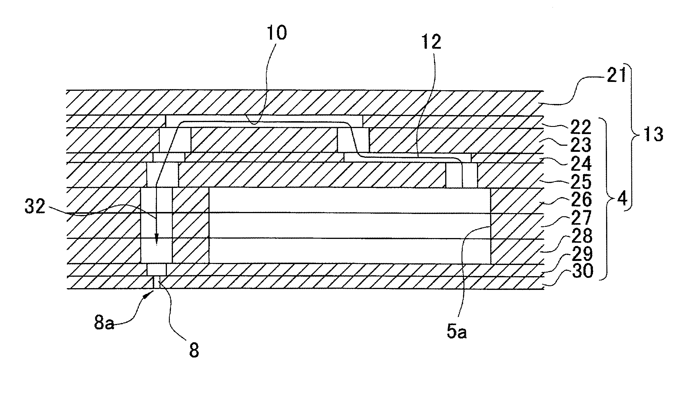
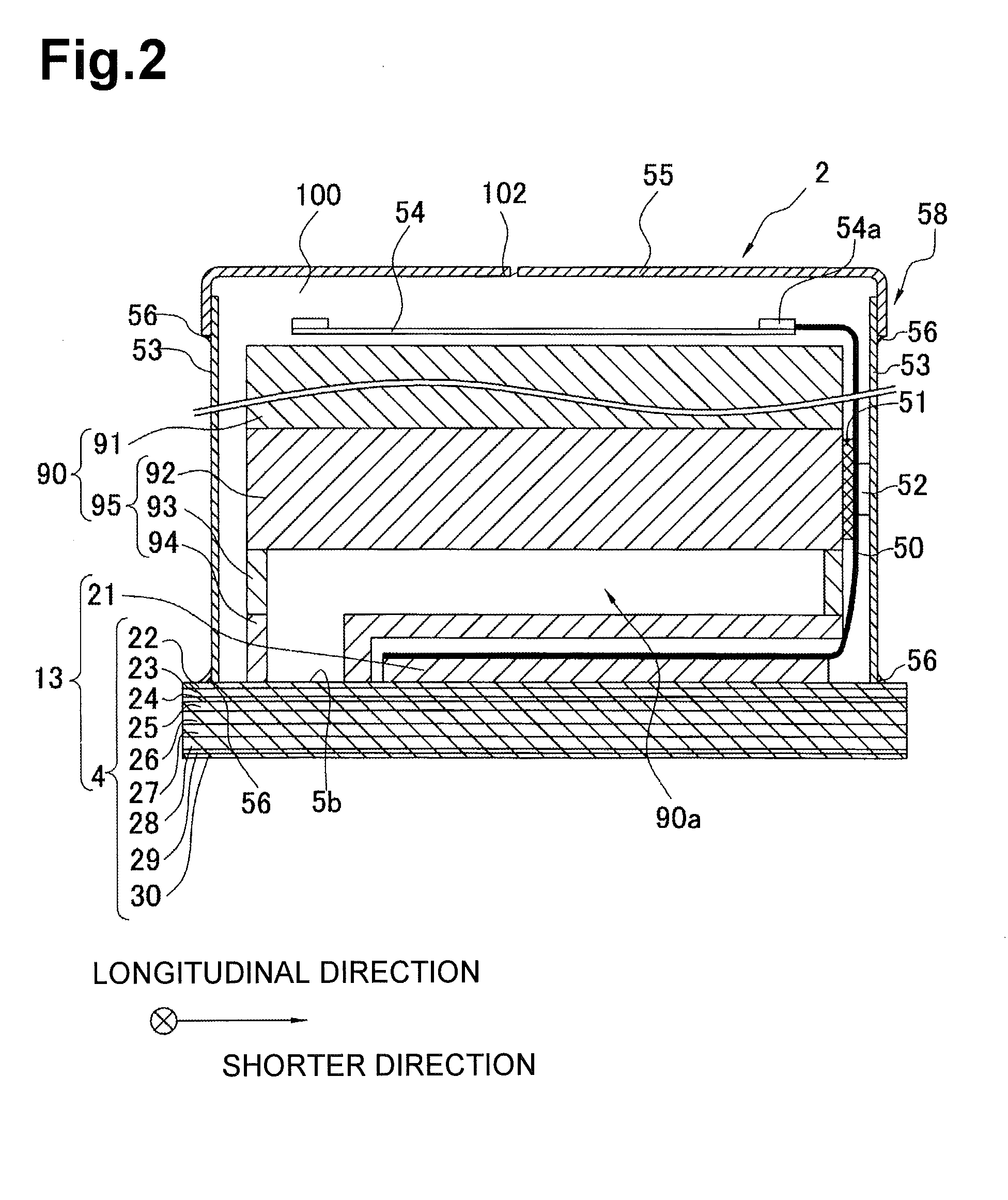
[0032]Next, the configuration of the entire ink-jet head 2 will be outlined below. FIG. 2 is a vertical sectional view of the ink-jet head 2. As shown in FIG. 2, the ink-jet head 2 is provided with a head main body 13 including a channel unit 4 and a piezoelectric actuator 21, a reservoir unit 90 which is disposed on the top surface of the head main body 13 and supplies ink to the head main body 13, a flexible printed circuit board (hereinafter abbreviated as FPC) 50 which is mounted with a driver IC 52 for supplying drive signals to piezoelectric actuators 2...

second embodiment

[0088]Although the lip 173 of the second embodiment is such that the two longer portions which expend parallel with the longitudinal direction of the plate member 171 serve as the first portion and the second portion, respectively, the two shorter portions which expend parallel with the shorter direction of the plate member 171 may serve as a first portion and a second portion, respectively. Another modification is possible in which the corner portion serve as first portions and second portions. Still another modification is possible in which parts of the two longer portions which expend parallel with the longitudinal direction of the plate member 171 or parts of the two shorter portions which expend parallel with the shorter direction of the plate member 171 serve as first portion(s) and second portion(s).

[0089]In addition, whereas in the second embodiment the first portion and the second portion are defined by the angle formed by the inner side surface of the tip portion of the li...


PUM


Abstract

A head cap for protecting an ink ejecting face of an ink-jet head may be provided with a plate member. The plate member may be opposed to the ink ejecting face. The head cap may include a flexible, continuous lip, which projects from one surface of the plate member. Recesses may be formed in the one surface of the plate member. Through-holes may be formed through the bottom walls of the recesses, respectively. Films may further be used where each covers the associated through-hole and is joined partially to a circumferential edge portion of the associated recess.

Description

RELATED APPLICATION[0001]This application claims priority to Japanese Application No. 2006-258420, filed Sep. 25, 2006, whose contents are expressly incorporated by reference.BACKGROUND[0002]1. Field[0003]Aspects of the present invention relate to a cap and an ink-jet head protection assembly for protecting the jets during transport, for example, of an ink-jet head.[0004]2. Description of the Related Art[0005]Ink-jet heads that are used for ejecting ink droplets from the jets are known in which the jets are protected while they are transported or kept in storage. In one example of a recording head (ink-jet head), the recording head is kept in storage after a seal made of an acrylic adhesive is brought into close contact with the ink ejecting face and the recording head is put into a storage box made of conductive polystyrene and sealed in an aluminum pouch.[0006]However, in this example, while the seal is kept in close contact with the ink ejecting face, the adhesive of the seal is ...

Claims


Application Information

Patent Timeline
IPC IPC(8): B41J2/165
CPCB41J2/16508
Inventor CHIKAMOTO, TADANOBUTAIRA, HIROSHI
Owner BROTHER KOGYO KK
Why Eureka
Try Eureka