Chain saw

A technology of chainsaw and sprocket, which is applied to chainsaws, sawing components, sawing equipment, etc., can solve problems such as difficulty in applying force by operators and uncomfortable operation.

Active Publication Date: 2010-08-25
POSITEC POWER TOOLS (SUZHOU) CO LTD
View PDF1 Cites 17 Cited by
  • Summary
  • Abstract
  • Description
  • Claims
  • Application Information

AI Technical Summary

Problems solved by technology

However, this structure makes the operation not very comfortable in some cases. For example, when it is necessary to cut high branches, it is more difficult for the operator to apply force; in addition, when it is necessary to cut wood placed on the ground, the operator needs to bend Work with your lower back, which can easily tire you if you work for a long time

Method used


Image

  • Chain saw
  • Chain saw
  • Chain saw

Examples


no. 1 approach

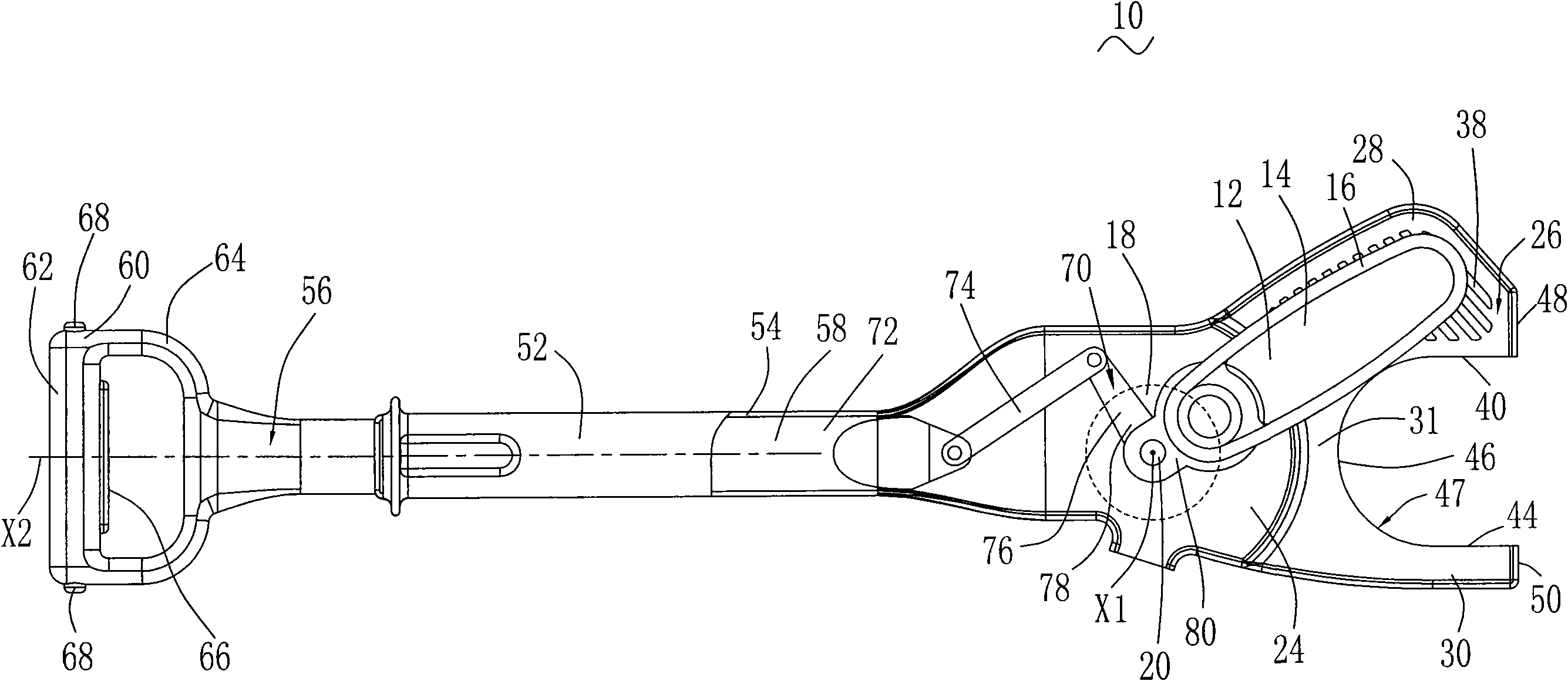
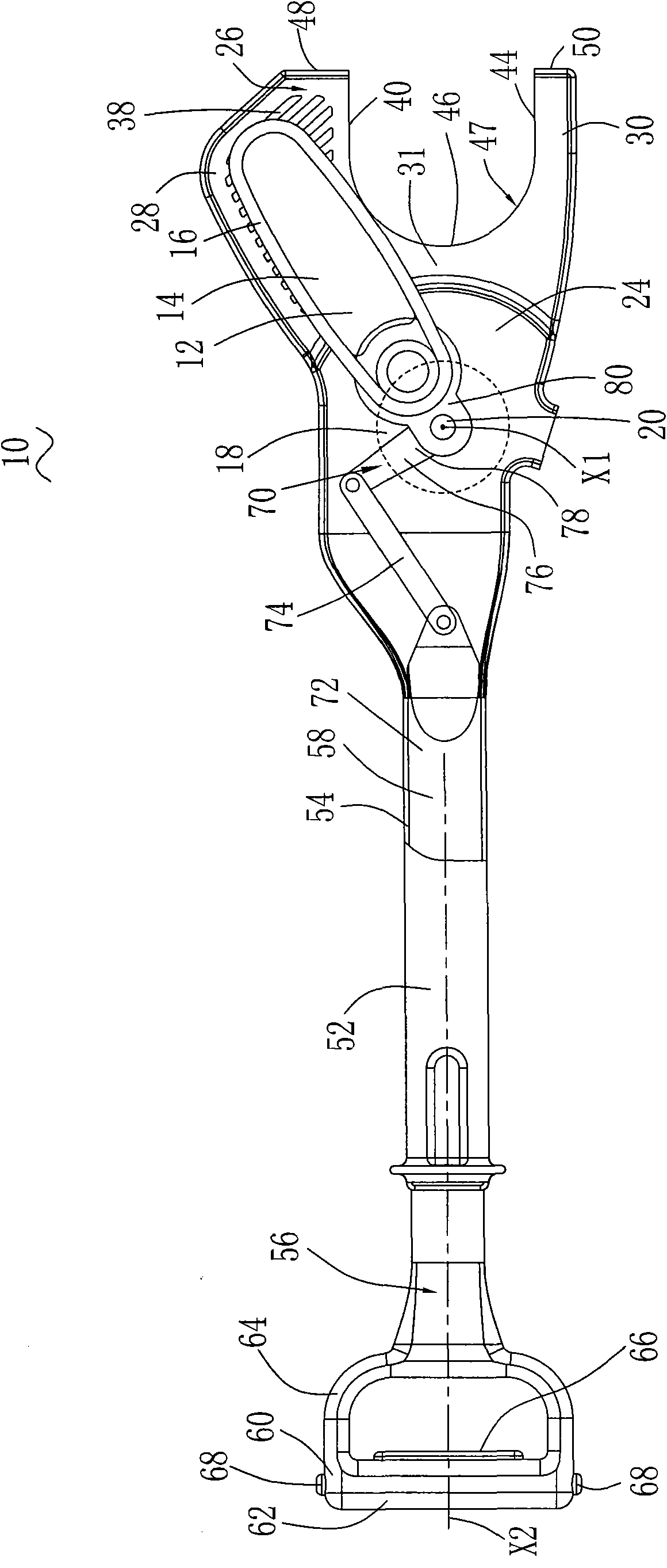
[0066] Referring to FIGS. 1-2 , a chainsaw 10 includes a working head 12 for machining workpieces. The working head 12 includes a support plate 14 and a cutting element mounted on the support plate 14 . In this embodiment, the cutting element is a flexible chain 16 which is installed on the periphery of the support plate 14 and can rotate around the support plate 14 . The plane where the support plate 14 is located is the support plate plane.

[0067] Chainsaw 10 also includes a motor 18 for driving working head 12 such that flexible chain 16 rotates about support plate 14 . The motor 18 has a motor output shaft 20 having a motor output shaft axis X1 which rotates about the motor output shaft axis X1 to drive the flexible chain 16 in rotation about the support plate 14 .

[0068] The motor 18 is accommodated in a motor housing 24. In this embodiment, the motor housing 24 is composed of two half shells. Of course, the motor housing is not limited to this form, and may be other...

no. 2 approach

[0082] Referring to FIG. 8 , this embodiment is basically the same as the first embodiment, except that the slider crank mechanism 70 is replaced by a rack and pinion mechanism 70a. The rack-and-pinion mechanism 70a includes a rack 72a fixedly connected to the handle device 56, and a gear 74a fixedly connected to the support plate 14. By pushing or pulling the handle device 56, the gear 74a will pivot to drive the support plate 14 to pivot. .

no. 3 approach

[0084]Referring to FIG. 9 , this embodiment is basically the same as the first embodiment, except that the slider crank mechanism 70 is replaced by a pulley mechanism 70b. The pulley mechanism 70b includes a pulley 72b and a rope 74b. The rope 74b is sheathed on the pulley 72b. One end of the rope 74b is fixedly connected to the handle device 56, and the other end of the rope 74b is fixedly connected to the motor housing 24. The pulley 72b is connected to the pulley 72b through the connecting rod 76b. The support plate 14 is fixedly connected. During operation, the operator pulls the handle device 56 along the C direction, and the pulley 72b drives the connecting rod 76b to pivot, so that the connecting rod 76b drives the support plate 14 to pivot.


PUM


Abstract

The invention provides a chain saw, comprising a cutting element, a supporting plate, a motor, a motor shell, a guide mechanism, a handle device and a connection mechanism, wherein the supporting plate provided with a supporting plate plane is used for supporting the cutting element, and can pivot around a fixed axis in the supporting plate plane; the motor is provided with a motor output shaft for rotating a drive cutting element; the motor shell is used for accommodating the motor; the chain saw also comprises the guide mechanism connected with the motor shell which is provided with a longitudinal extending axis; the handle device does linear motion operatively along the longitudinal extending axis of the guide mechanism; the handle device is connected with the supporting plate through the connection mechanism; and the connection mechanism converts the linear motion of the handle device into the pivoting motion of the supporting plate. The handle device does linear motion, so an operator feels comfortable no matter the operation is carried out along any direction, and is not easy to feel fatigue.

Description

technical field [0001] The invention relates to a power tool, in particular to a chain saw. Background technique [0002] At present, there are many tools for pruning plants on the market, such as scissors for pruning some relatively small branches and leaves. There are also pruners and chain saws that are usually used to trim relatively thick trees and so on. [0003] A traditional chainsaw includes a working head consisting of a chain and a support plate used to support the chain. The chain is driven by a motor and rotates around the support plate. The traditional chainsaw also includes a main handle located at the rear of the work head. Auxiliary handle between head and main handle. When cutting, the working head of this traditional chain saw is usually only driven by the motor so that the chain rotates around the support plate, and the support plate is generally stationary. During the cutting process, the operator holds the main handle with one hand and the auxiliary h...

Claims


Application Information

Patent Timeline
Patent Type & Authority Applications(China)
IPC IPC(8): B27B17/02B27B17/08B27G19/00A01G3/08
Inventor 沃伦·布朗哈利·索默格雷厄姆·格哈德
Owner POSITEC POWER TOOLS (SUZHOU) CO LTD
Why Eureka
Try Eureka