Bifurcate lap connection of reinforcing steel bars and connection method thereof

A technology of lap joint connection and connection method, which is applied in the processing of building materials, structural elements, building components, etc., can solve problems affecting the mechanical performance of steel bars, steel bar layout schemes, prefabricated concrete component production and construction complexity, etc., to achieve The effect of mechanical performance and reinforcement layout optimization, easy guarantee of construction quality and cost reduction

Active Publication Date: 2010-08-25
HEILONGJIANG YUHUI NEW BUILDING MATERIAL
View PDF0 Cites 26 Cited by
  • Summary
  • Abstract
  • Description
  • Claims
  • Application Information

AI Technical Summary

Problems solved by technology

Among them, the lap joint connection of grouted steel bars with reserved holes is the simplest, but the axis center of the connected steel bar and the connecting steel bar cannot be aligned when the traditional steel bar lap joint is connected, which will affect the mechanical performance of the steel bar and the layout of the steel bar, resulting in the production of precast concrete components. construction complexity

Method used


Image

  • Bifurcate lap connection of reinforcing steel bars and connection method thereof
  • Bifurcate lap connection of reinforcing steel bars and connection method thereof

Examples


Embodiment 1

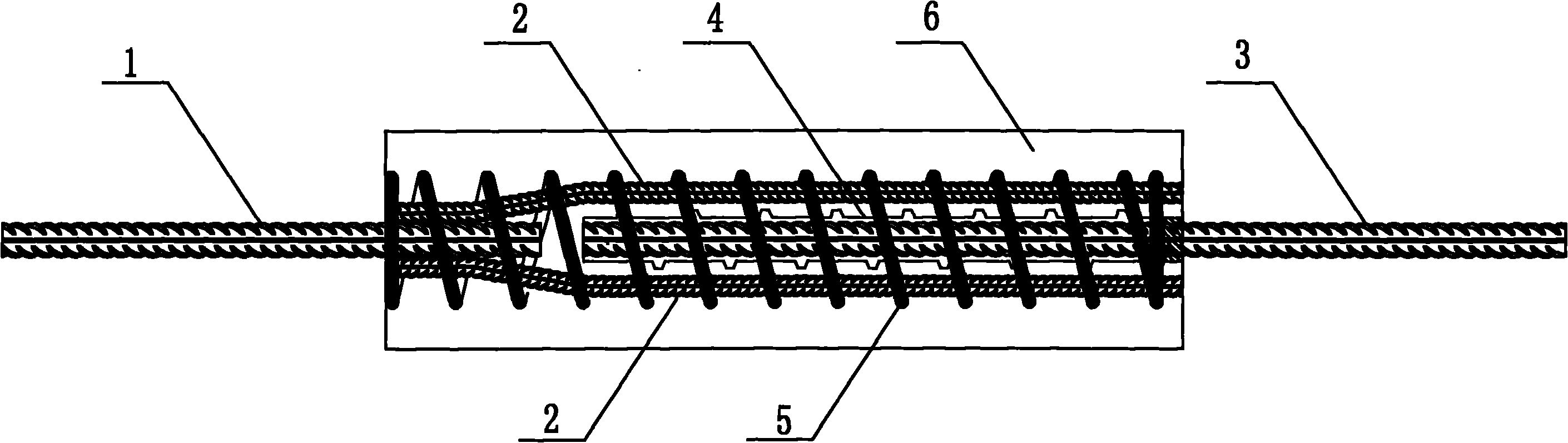
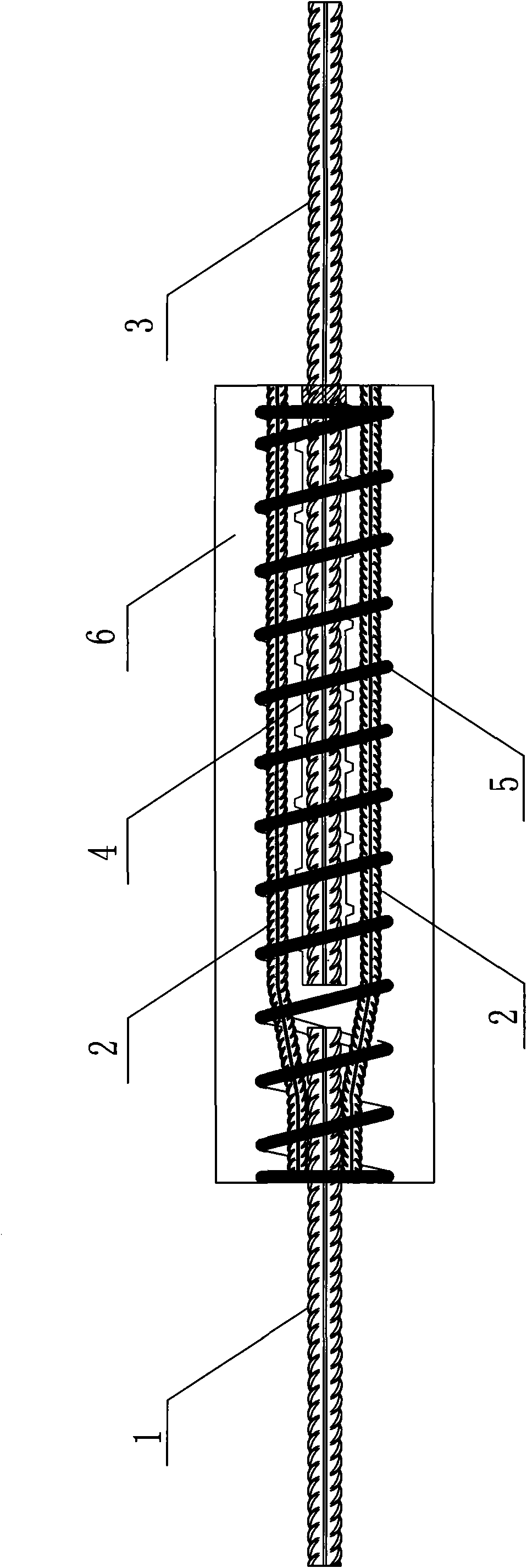
[0018] The steel bar bifurcated lap connection, its composition includes: the connected steel bar 1, the connected steel bar is connected with the bifurcated steel bar 2, and there is a reserved hole 4 concentric with the axis of the connected steel bar in the middle of the bifurcated steel bar. There is a connecting steel bar 3 in the reserved hole, a spiral reinforcing bar 5 is arranged on the outer circumference of the bifurcated steel bar in the axial direction, and concrete 6 is provided in the bifurcated steel bar section, as shown in the accompanying drawings.

[0019] For the bifurcated and overlapped connection of the reinforcing bars, the sum of the cross-sectional areas of the bifurcated reinforcing bars is equal to the area of ​​the connected reinforcing bars or the connecting reinforcing bars.

[0020] The said reinforcing bar is bifurcated and overlapped, and said bifurcated reinforcing bar can be divided into two forks according to requirements, and each fork is ...

Embodiment 2

[0022] For the above-mentioned forked connection of steel bars, the said forked steel bars can be divided into three, four, five or six forks according to requirements, and each fork is evenly distributed around the connecting steel bars.

Embodiment 3

[0024] The connection method of the steel bar bifurcation lap connection includes the following steps:

[0025] a. Connect the bifurcated steel bar to the end of the connected steel bar by lap welding or special steel threaded connectors, and reserve a reserved hole concentric with the center of the connected steel bar in the middle of the bifurcated steel bar;

[0026] b. Insert connecting steel bars in the reserved holes, and arrange spiral reinforcing bars on the outer circumference of the bifurcated steel bars.

[0027] c. Pour concrete into the bifurcated steel bars.


PUM


Abstract

The invention discloses bifurcate lap connection of reinforcing steel bars and a connection method thereof. In the traditional construction industry, the axes of the reinforcing steel bar connected by lapping is not centered to affect the stress performance. The bifurcate lap connection of the reinforcing steel bar comprises a reinforcing steel bar (1) to be connected, the reinforcing steel bar to be connected is connected with a bifurcate reinforcing steel bar (2), the middle of the bifurcate reinforcing steel bar is provided with a prepared hole (4) which is concentric with the axes of the reinforcing steel bar to be connected, a connecting reinforcing steel bar (3) is arranged in the prepared hole, the periphery of the bifurcate reinforcing steel bar is provided with a spiral reinforced rib (5) along the axial direction, and the bifurcate reinforcing steel bar section is provided with concrete (6). The invention is used for lapping and connecting the reinforcing steel bar between prefabricated concrete structures.

Description

Technical field: [0001] The invention relates to a steel bar connection of a prefabricated concrete structural component, in particular to a steel bar bifurcation lap joint connection and a connection method thereof. Background technique: [0002] In the prefabricated concrete structure, the connection of steel bars is usually made of lap joint connection of reserved hole grouting steel bar or connection method of metal sleeve. Among them, the lap connection of grouted steel bars with reserved holes is the simplest, but the axis center of the connected steel bar and the connecting steel bar cannot be centered during the traditional steel bar lap connection, which will affect the mechanical performance of the steel bar and the layout of the steel bar, resulting in the production of precast concrete components. Complexity of construction. Invention content: [0003] The object of the present invention is to provide a kind of steel bar bifurcation lap joint connection and it...

Claims


Application Information

Patent Timeline
Patent Type & Authority Applications(China)
IPC IPC(8): E04C5/16E04G21/12
Inventor 刘文清姜洪斌闫红缨耿伟常
Owner HEILONGJIANG YUHUI NEW BUILDING MATERIAL
Why Eureka
Try Eureka