

Gasoline engine lubricating structure
A lubricating structure and gasoline engine technology, applied in the direction of engine lubrication, pressure lubricants, mechanical equipment, etc., can solve the problems affecting the smooth flow of lubricating oil circulation, poor sensitivity and reliability, and increase the work efficiency of the assembled machine to achieve guarantee Good patency, reliability and good lubricating effect
Inactive Publication Date: 2010-08-25
力帆科技(集团)股份有限公司
View PDF6 Cites 0 Cited by
- Summary
- Abstract
- Description
- Claims
- Application Information
AI Technical Summary
Problems solved by technology
The traditional gasoline engine uses a one-way valve composed of a stopper and a valve plate to control the opening and closing of the oil circuit between the crank chamber and the crankshaft gear chamber. Due to the small size of the stopper and the valve plate, the installation is more difficult, which will increase the work efficiency of assembling the whole machine
At the same time, the valve plate is a steel plate, which requires a certain pressure to open, and the sensitivity and reliability are poor, which easily affects the smoothness of the lubricating oil circulation, thereby reducing the effect of the lubrication of the whole machine
Method used
View moreImage
Smart ImageViewing Examples


Examples
Embodiment Construction
Login to View More PUM
 Abstract
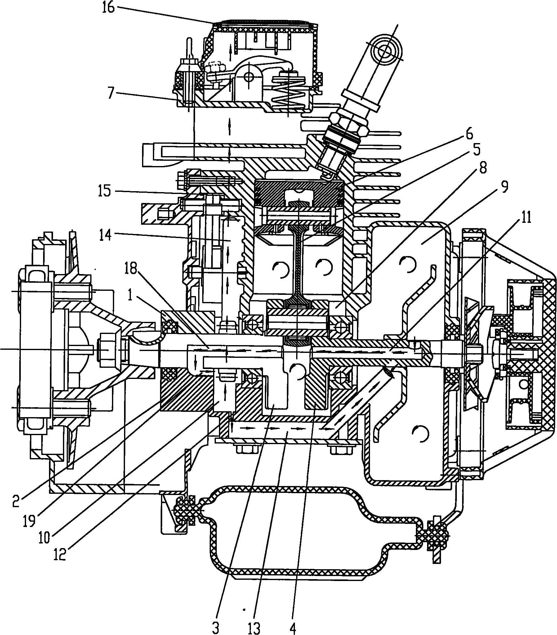
The invention discloses a gasoline engine lubricating structure. Upper and lower crankshaft cases are combined to form a crank chamber, an engine oil chamber and a crankshaft gear chamber; the engine oil chamber is positioned on the right side of the crank chamber and communicated with the crank chamber through a first oil guide passage on a right crank; the crankshaft gear chamber is positioned on the left side of the crank chamber; the bottom of the crankshaft gear chamber is provided with a small hole which is communicated with an oil return passage on the lower crankshaft case; a left crank is provided with a second oil guide passage of which the oil inlet is formed on the end face of the handle part of the left crank; the oil outlet of the second oil guide passage is formed on the outer circumferential surface of the shaft part of the left crank and can be communicated with the crankshaft gear chamber through a third oil guide passage on the lower crankshaft case. The structure can improve the flexibility and reliability for opening or closing the passage between the crank chamber and the crankshaft gear chamber, ensure the smoothness for circular flowing of the lubricating oil and have the characteristics of skillful design, simple structure, low reconstruction cost, good lubricating effect and the like.
Description
technical field The invention belongs to the technical field of general-purpose gasoline engines, and in particular relates to a lubrication system for general-purpose gasoline engines. Background technique The upper and lower crankcases of the general-purpose gasoline engine are combined to form a crank chamber, an oil chamber and a crank gear chamber. The oil chamber is located on the right side of the crank chamber. There is an oil hole connected to the crankshaft gear chamber at the bottom of the crank chamber. A stopper and a valve plate are installed in the oil hole. The stopper and valve plate act as a check valve to ensure that the lubricating oil flows from the Chamber to crankshaft gear chamber unidirectional flow. The crank gear chamber is located on the left side of the crank chamber, and the bottom of the crank gear chamber has a small hole to communicate with the oil return passage on the lower crankcase, and a cam connected to it is arranged above the crank g...
Claims
Login to View More Application Information
Patent Timeline
 IPC IPC(8): F01M1/04
Inventor罗元波程应维
Owner力帆科技(集团)股份有限公司