Flow control valve

A flow control valve and fluid technology, applied in sliding valves, valve details, valve devices, etc., can solve the problems of low efficiency, complex structure, high cost, and achieve the effect of low noise and no magnetic field interference

Inactive Publication Date: 2010-08-25
SIEMENS CHINA
View PDF2 Cites 7 Cited by
  • Summary
  • Abstract
  • Description
  • Claims
  • Application Information

AI Technical Summary

Problems solved by technology

Positioning screws and steel balls help the rotation of the motor output shaft into the vertical movement of the valve stem, and its structure is relatively complicated
US 4840350 A discloses an exhaust ga

Method used


Image

  • Flow control valve
  • Flow control valve
  • Flow control valve

Examples


Example Embodiment

[0040] In order to have a clearer understanding of the technical features, objectives and effects of the present invention, specific embodiments of the present invention will now be described with reference to the accompanying drawings. Among them, the same parts use the same reference numerals.

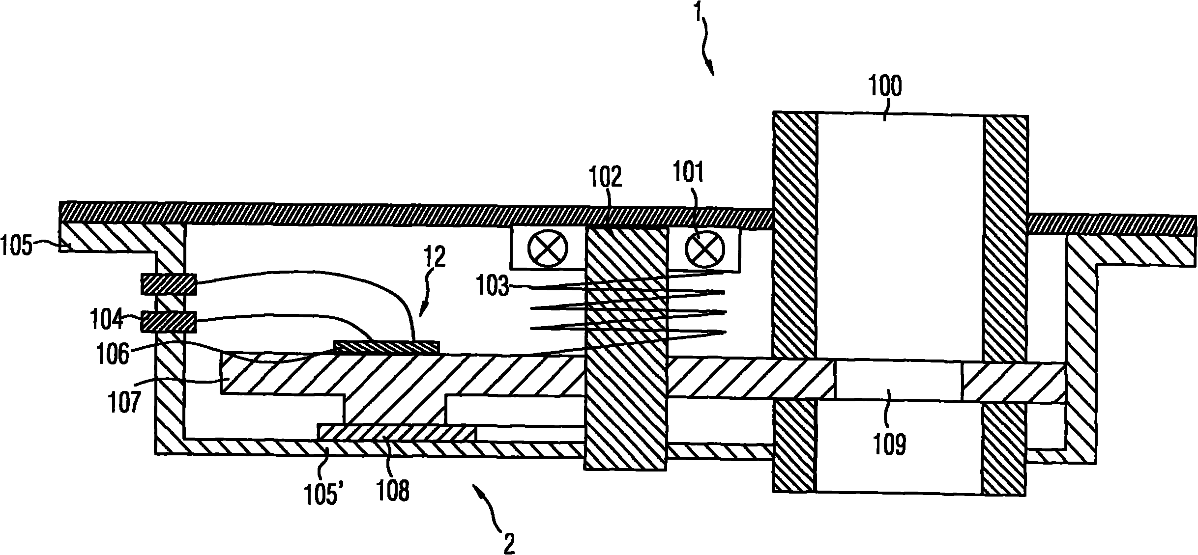
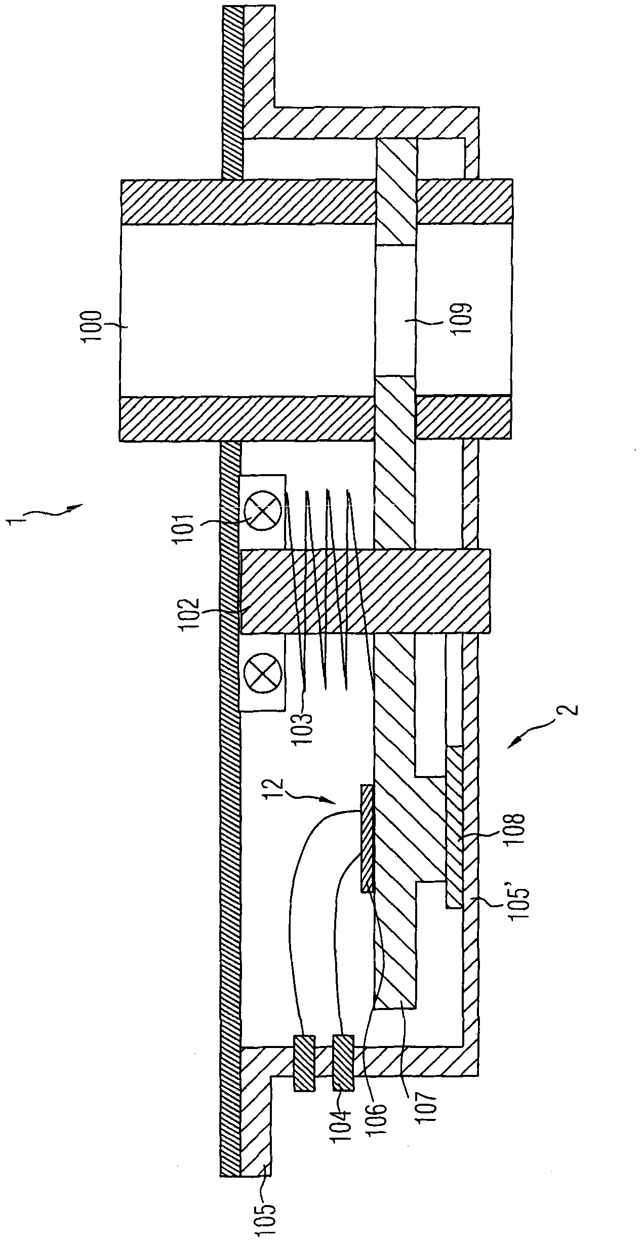
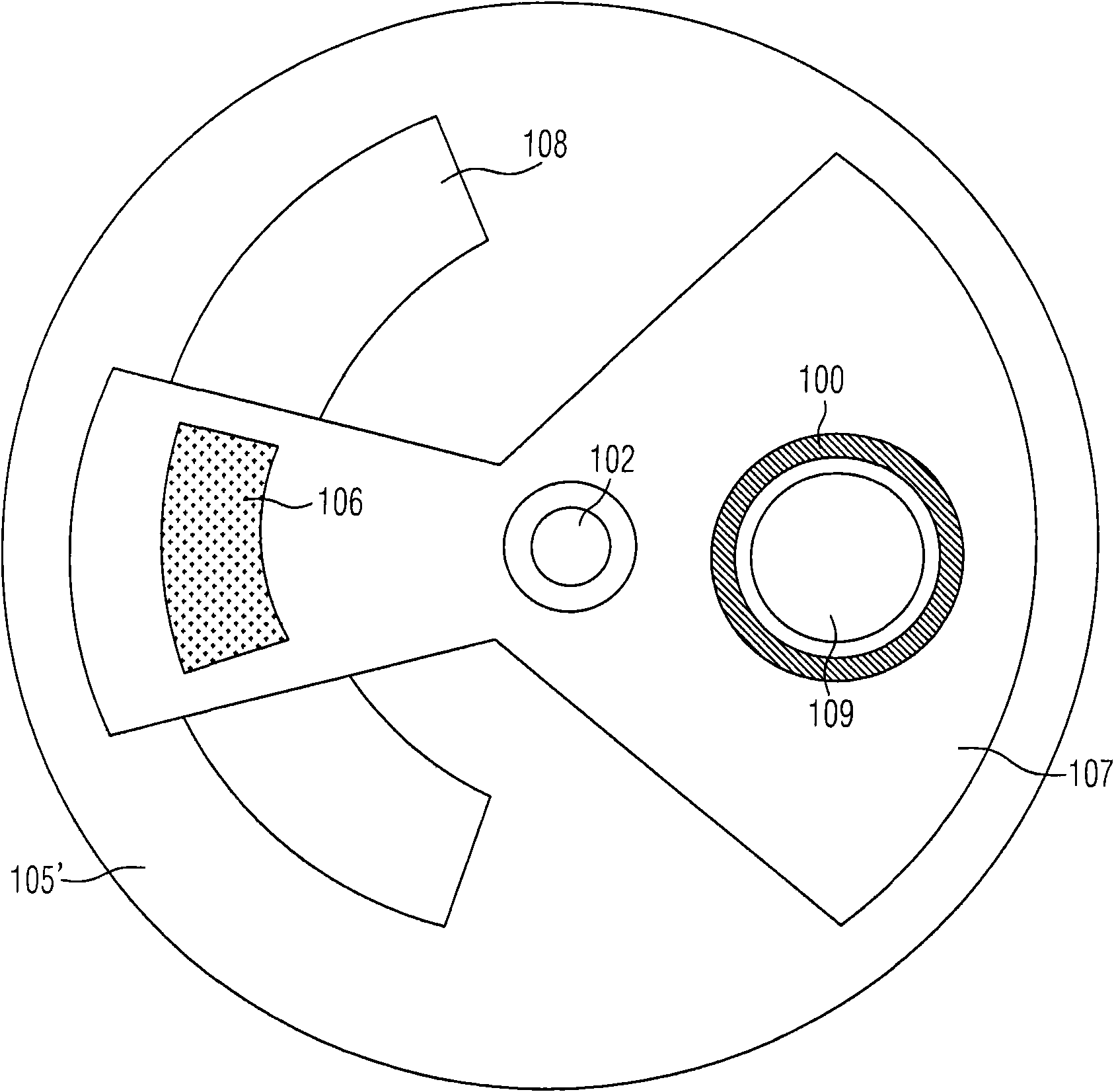
[0041] Fig. 1 is a schematic cross-sectional view of a flow control valve according to a specific embodiment of the present invention. As shown in the figure, the flow control valve 1 of this embodiment has a pipe 100 through which fluid passes. A rotating piece 107 that cuts off the pipe 100 is arranged along the vertical direction of the pipe 100. The rotating piece 107 is provided with at least one rotating piece 107 that can rotate to and The opening 109 of the pipe 100 overlaps, wherein the diameter of the opening 109 is not greater than the outer diameter of the pipe 100.

[0042] It can be seen from the figure that the pipe 100 is actually composed of two parts separated by a rota...


PUM


Abstract

The invention provides a flow control valve, which can be used for flow control in an exhaust gas recirculation pipeline of an internal combustion engine. The flow control valve is provided with a pipe communicating the pipeline, wherein a rotary plate for blocking the pipe is arranged along the vertical direction of the pipe; at least one opening is reserved on the rotary plate; the rotary plate can rotate to the position where the opening and the pipe are superposed; the diameter of the opening is not greater than the outer diameter of the pipe; and a drive mechanism can drive the rotary plate to rotate around the axis of a rotating shaft and the drive mechanism can be a piezoelectric drive mechanism. The flow control valve has the advantages of compact and simple structure, smart size, low energy consumption, low noise and easy and accurate flow adjustment.

Description

technical field [0001] The invention relates to a flow control valve, in particular to a flow control valve which can be used in an exhaust gas recirculation pipeline of an internal combustion engine. Background technique [0002] The harmful emissions of the engine are a major source of air pollution. In order to reduce harmful gas emissions, an exhaust gas recirculation (EGR) system is usually installed on the internal combustion engine, which recirculates a part of the exhaust gas from the exhaust passage to the intake passage to reduce engine emissions. The EGR system can effectively reduce the combustion temperature of the engine, thereby effectively reducing the content of toxic substances such as nitrogen oxides in exhaust gas. [0003] The EGR system mainly includes an exhaust gas recirculation pipeline and an exhaust gas recirculation valve, the exhaust gas recirculation pipeline is used to guide the exhaust gas from the exhaust passage to recirculate into the inta...

Claims


Application Information

Patent Timeline
IPC IPC(8): F16K3/08F16K31/02F02M25/07F02M26/65
CPCY02T10/121Y02T10/12
Inventor 张明亮
Owner SIEMENS CHINA
Why Eureka
Try Eureka