Wireless detonator component, explosive device and exploding method thereof
A technology of wireless detonators and components, applied in blasting, fuzes, weapon accessories, etc., to avoid misuse of detonators, reduce time and cost, and improve safety
Inactive Publication Date: 2010-08-25
北京维深数码科技有限公司
View PDF6 Cites 15 Cited by
- Summary
- Abstract
- Description
- Claims
- Application Information
AI Technical Summary
Problems solved by technology
However, there are still major safety problems in the existing wireless detonation system. If the wireless detonator detonation system is to actually replace the traditional "wired" detonation system, the existing wireless detonation system needs to be improved.
Method used
View moreImage
Smart ImageViewing Examples
Examples
Embodiment Construction
Login to View More PUM
 Abstract
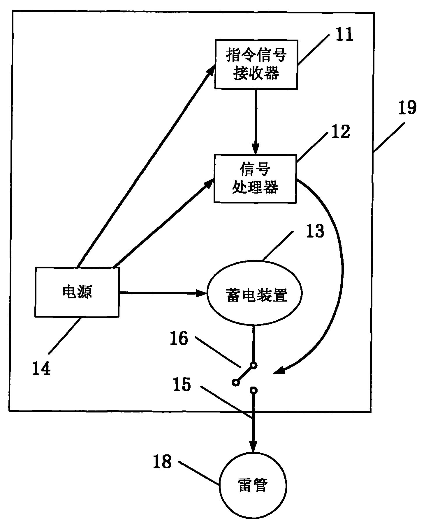
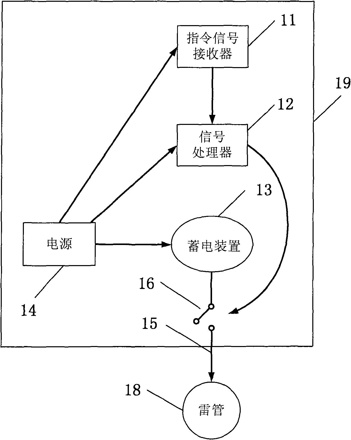
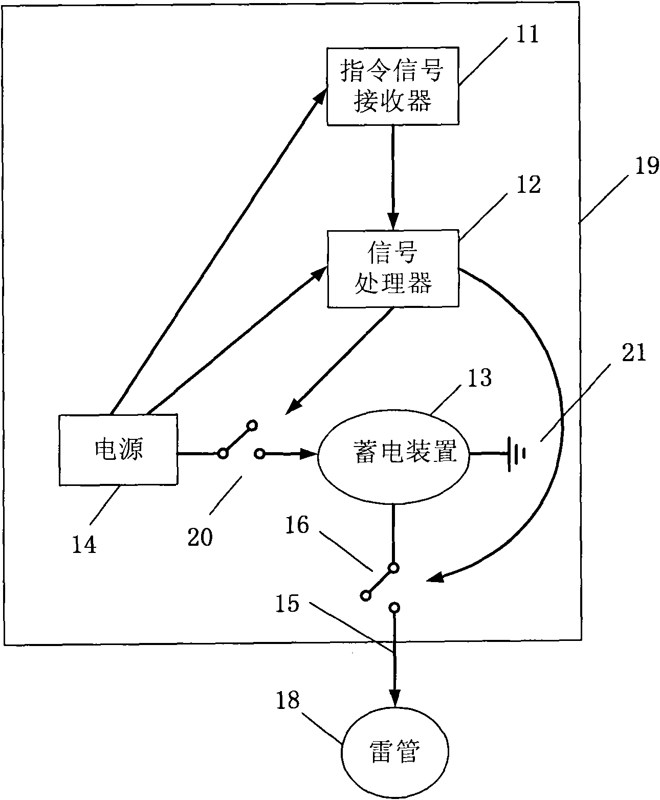
The embodiment of the invention provides a wireless detonator component, which comprises a detonator with basic explosive load, a signal receiving processor, an electrical storage device, a power supply and an ignition circuit, wherein the signal receiving processor is used for receiving and processing wireless control signals sent by an exploder; the electrical storage device is used for providing power; the at least one power supply supplies power to the signal receiving processor and charges the electrical storage device; the power supply has enough energy to ignite an explosive package; the ignition circuit is connected with the electrical storage device; and when a receiver receives an ignition command, the electrical storage device discharges to the ignition circuit to explode the explosive package. The invention also provides an explosive device and an exploding method on the blast scene. The time and cost required by explosion operation can be reduced, and the safety is integrally improved.
Description
A wireless detonator assembly, blasting device and detonation method thereof technical field The invention relates to the technical field of blasting, in particular to the field of wireless detonator components and a detonation method. Background technique In mining operations, relying on explosive charges to directly break rock requires a great deal of skill and expertise. In most mining operations the appropriate amount of explosive charge is manually placed into the rock at a pre-selected location and the detonator detonates the charge after a predetermined delay time to break the rock in the desired blast pattern. Traditionally, the signal is transmitted from the combined detonator to the detonator through a non-electric system using a low-energy detonating cord (LEDC, Low Energy Detonating Cord) or detonator. The wire can choose one of the electronic detonators to transmit more complex signals. For example, this signal may include an arm command (ARM), a de-arm comma...
Claims
Login to View More Application Information
Patent Timeline
 IPC IPC(8): F42C19/12F42C13/04F42C13/02F42D1/00F42D1/045F42D1/055
Inventor 李长军李代万王大志董蓓郑兴旺
Owner 北京维深数码科技有限公司
- R&D Engineer
- R&D Manager
- IP Professional
- Industry Leading Data Capabilities
- Powerful AI technology
- Patent DNA Extraction
Learn More Browse by: Latest US Patents, China's latest patents, Technical Efficacy Thesaurus, Application Domain, Technology Topic, Popular Technical Reports.
© 2024 PatSnap. All rights reserved.Legal|Privacy policy|Modern Slavery Act Transparency Statement|Sitemap|About US| Contact US: help@patsnap.com


