Diagnostic equipment for fault points of control circuit

A diagnostic device and control loop technology, applied in the direction of electrical testing/monitoring, etc., can solve problems such as high cost, misjudgment of faults, failure to respond to fault states, etc., and achieve the effect of low cost and simple and applicable circuit structure

Inactive Publication Date: 2010-08-25
SHANGHAI MEISHAN IRON & STEEL CO LTD
View PDF0 Cites 1 Cited by
  • Summary
  • Abstract
  • Description
  • Claims
  • Application Information

AI Technical Summary

Problems solved by technology

However, the PLC (programmable logic controller) system is not only costly, but its input signal is the conversion signal of the relay or the actuator, which is not a real control loop point signal, and

Method used


Image

  • Diagnostic equipment for fault points of control circuit
  • Diagnostic equipment for fault points of control circuit
  • Diagnostic equipment for fault points of control circuit

Examples


Embodiment 1

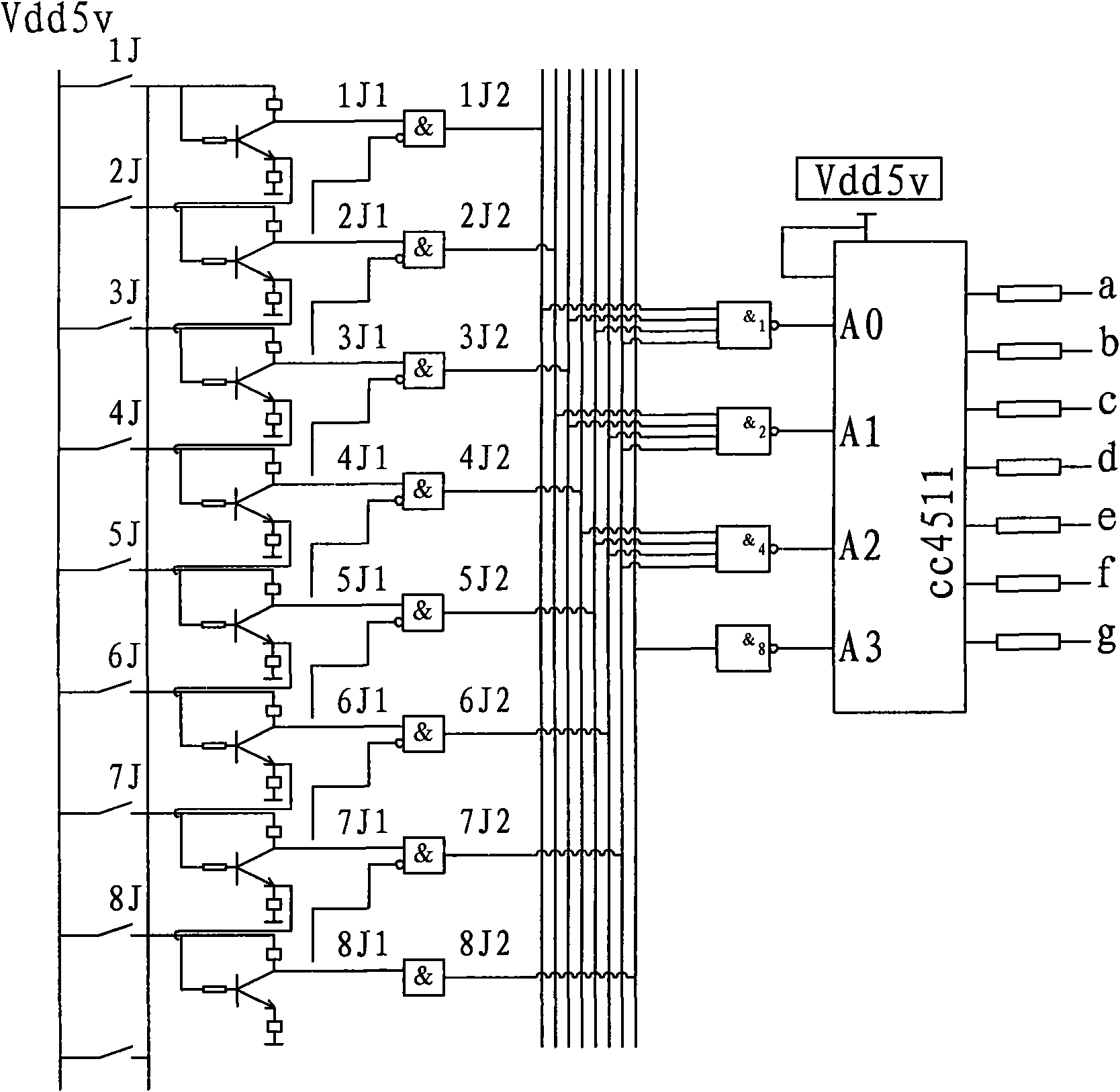
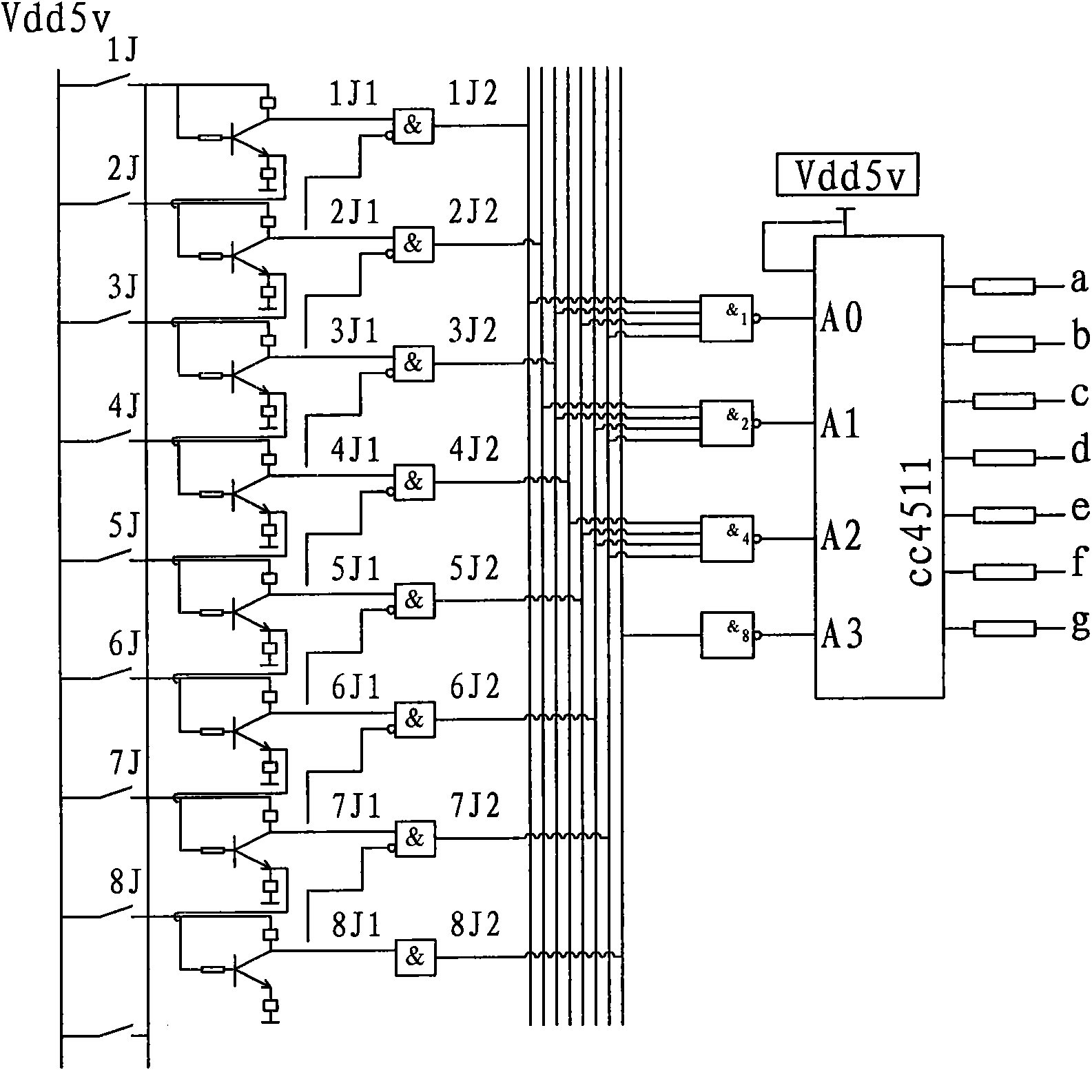
[0016] The device for diagnosing the fault point of the control loop in this embodiment is shown in Figure 2, which includes a group of eight relays 1J to 8J connected to the connection terminals of each control point in sequence, forming a multi-level channel. The output ends of the relays at all levels are respectively connected to the corresponding triode collectors through the current limiting resistors, and at the same time connected to one of the corresponding input ends of the AND gates 1J1 to 8J1. Starting from the second-stage channel, the collectors of the triodes of each stage are reversed and connected to the other input terminal of the AND gate of the previous stage. Except for the last stage, the emitters of each level of triode are respectively connected to the base of the next stage of triode through base resistors. After the outputs of eight AND gates 1J2 to 8J2 of each level pass through the 8421BCD decoding circuit, they are connected to the seven-segment di...


PUM


Abstract

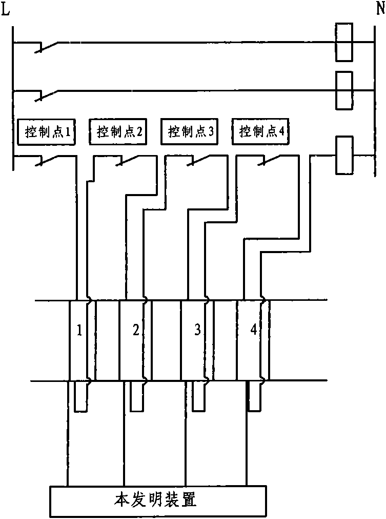
The invention relates to diagnostic equipment for fault points in an electrical control circuit, belonging to the technical field of circuit monitoring. The equipment comprises a group of relays connected to each control point terminal in parallel according to a certain sequence so as to form channels in multiple levels; the output end of the relay at each level is connected with a triode collector correspondingly and one input end of a conjunction gate at the same time; from the channel at the second level, the triode collector of each level is in reverse connection with the other input end of the conjunction gate at the previous level; except the final level, the emitter of the triode of each level is connected with the base of the triode at the next level; and the output of conjunction gates at different levels is connected with a digital display device via a coding circuit. As the equipment is connected on the control circuit terminal in parallel directly, an energy source of the control circuit is adopted directly to accurately reflect the operation condition of the control circuit, and especially indicates the fault position of the control circuit actually and timely. The circuit structure is simple and practicable, and has economic cost; and the fault of the circuit structure has no influence on the control circuit by means of the isolation of the relays.

Description

technical field [0001] The invention relates to a fault diagnosis device, in particular to a fault point diagnosis device of an electric control circuit, which belongs to the technical field of circuit monitoring. Background technique [0002] Due to the complex circuit and many control points of the electrical control circuit, it is often difficult to judge after a fault occurs. For example, the deviation switch control circuit of the belt material yard, because a belt is very long, there are many deviation switches, if a switch action occurs, the entire belt will stop running, and to find out which deviation switch action, it is necessary to pass A lot of precision inspection work can find the fault point. And a stock yard usually has dozens or even hundreds of belts, so it is more difficult to break down. In addition, the same is true for drawer cabinets similar to MCC, because all control circuits are placed in the electrical drawer. When a fault occurs, the electrical...

Claims


Application Information

Patent Timeline
IPC IPC(8): G05B23/02
Inventor 沈立春季益龙吉明鹏余云龙
Owner SHANGHAI MEISHAN IRON & STEEL CO LTD
Why Eureka
Try Eureka