

Driver fatigue monitor system based on infrared eye state identification
A fatigue driving and early warning system technology, applied in character and pattern recognition, alarms, instruments, etc., can solve problems such as poor reliability, large amount of calculation, and poor real-time performance
Active Publication Date: 2010-08-25
ZHEJIANG UNIV OF TECH
View PDF5 Cites 20 Cited by
- Summary
- Abstract
- Description
- Claims
- Application Information
AI Technical Summary
Problems solved by technology
In order to overcome the disadvantages of poor reliability, large amount of calculation, and poor real-time performance of the existing fatigue driving warning system, the present invention provides a fatigue driving warning system based on infrared eye recognition with good reliability, reduced calculation amount and good real-time performance
Method used
View moreImage
Smart ImageViewing Examples

Examples
Embodiment Construction
Login to View More PUM
 Abstract
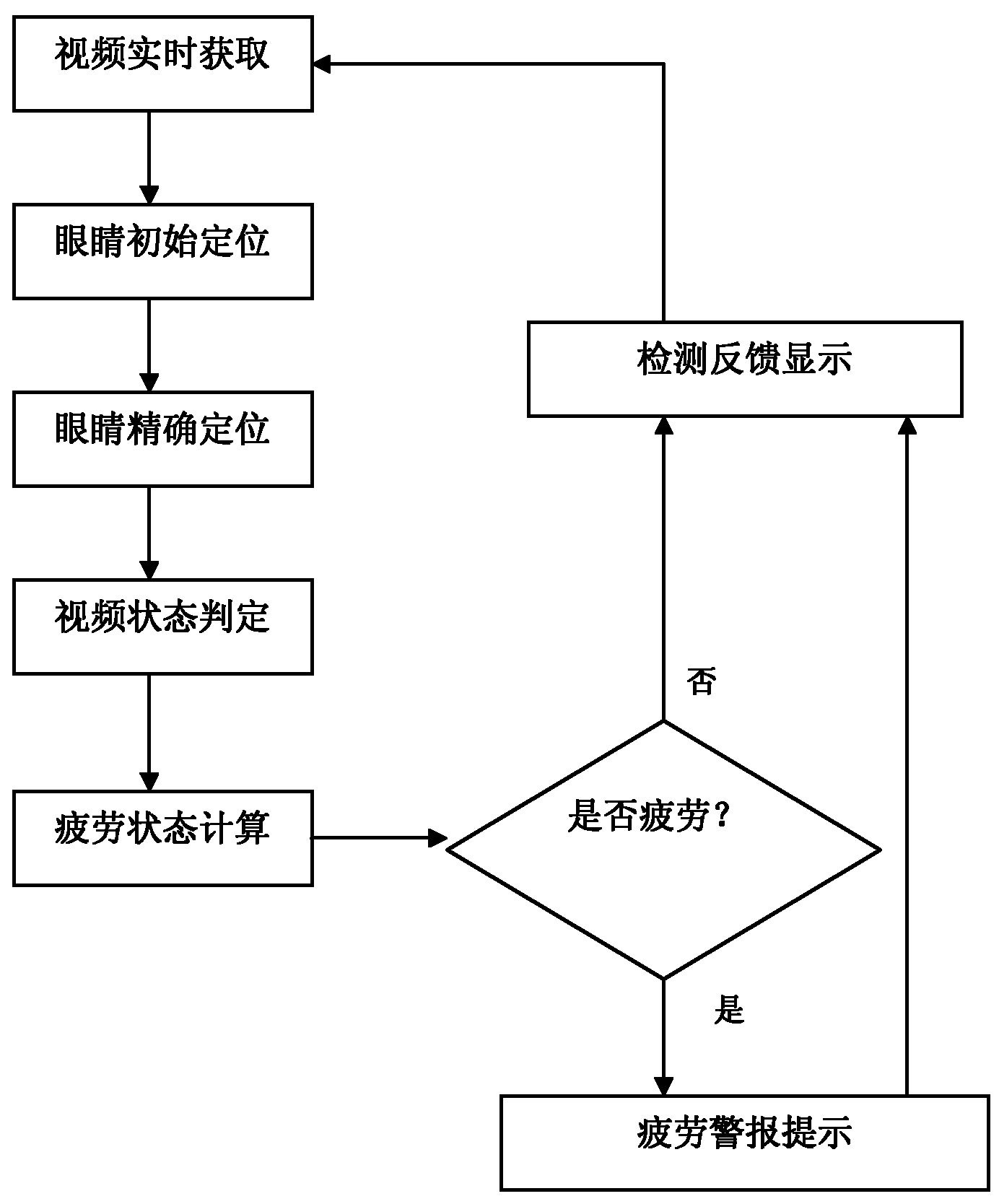
The invention relates to a driver fatigue monitor system based on infrared eye state identification, which comprises a video acquisition module, an eye initial positioning module, an eye tracking predicting module, an eye accurate positioning module, an eye state identifying module, a fatigue state computing module and a driver fatigue prewarning module, wherein the video acquisition module is used for acquiring a head video image of a driver; the eye initial positioning module is used for processing the head video image by adopting a background difference technology for initially positioningeyes; the eye tracking predicting module is used for tracking and predicting the positions of the eyes by adopting a kalman filter; the eye accurate positioning module is used for realizing accurate positioning of the final positions of the eyes by adopting an improved Mean-Shift of fusion infrared image space textures; the eye state identifying module is used for carrying out binary or edge detection on an eye region and obtaining length and width information of the eyes; the fatigue state computing module is used for judging eye fatigue state according to a P80 standard of PERCLOS in accordance with the eye state of a current detection time period; and the driver fatigue prewarning module is used for judging the current state as a fatigue state and sending a warning command. The invention has high reliability, relatively smaller computation amount of the system, and good real-time.
Description
technical field The invention relates to a fatigue driving monitoring system, in particular to a fatigue driving early warning system based on infrared eye state recognition. Background technique Using cameras and computer vision technology to detect driver fatigue through non-contact monitoring of the driver's visual behavior, this method is to extract visual features that can typically represent the driver's fatigue level from a driver's video image using computer vision The technology judges the fatigue state of the driver. After the driver's eyes are positioned, it is necessary to identify and judge the driver's eye state. The more commonly used eye state recognition methods are: (1) Sample learning method The sample learning method is the mainstream method of feature detection at present, but it is greatly affected by the learning samples, and different sample preparation methods will cause great differences in the performance of the same algorithm. For example, c...
Claims
Login to View More Application Information
Patent Timeline
 IPC IPC(8): G06K9/00G08B21/02
Inventor梁荣华田青毛剑飞郑博周德龙张培乐王云霄
OwnerZHEJIANG UNIV OF TECH