
VRRP and learning bridge CPE

A technology of virtual network and telecommunication network, applied in the direction of network connection, data exchange network, digital transmission system, etc., which can solve the problems of wasting local loops and gathering network bandwidth, occupation, etc.

Inactive Publication Date: 2010-08-25
TELEFON AB LM ERICSSON (PUBL)
View PDF3 Cites 8 Cited by
  • Summary
  • Abstract
  • Description
  • Claims
  • Application Information

AI Technical Summary

Problems solved by technology

The consequence is that an Ethernet bridge receiving an Ethernet frame from an upstream end-user host with the virtual router MAC address as the destination address will always flood the frame on all logical channels, wasting local loop and aggregation network ), and also unnecessarily occupy the MAC table in the aggregation network switch

Method used


Image

  • VRRP and learning bridge CPE
  • VRRP and learning bridge CPE
  • VRRP and learning bridge CPE

Examples


Embodiment Construction

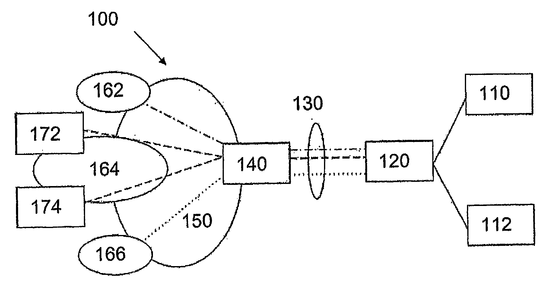
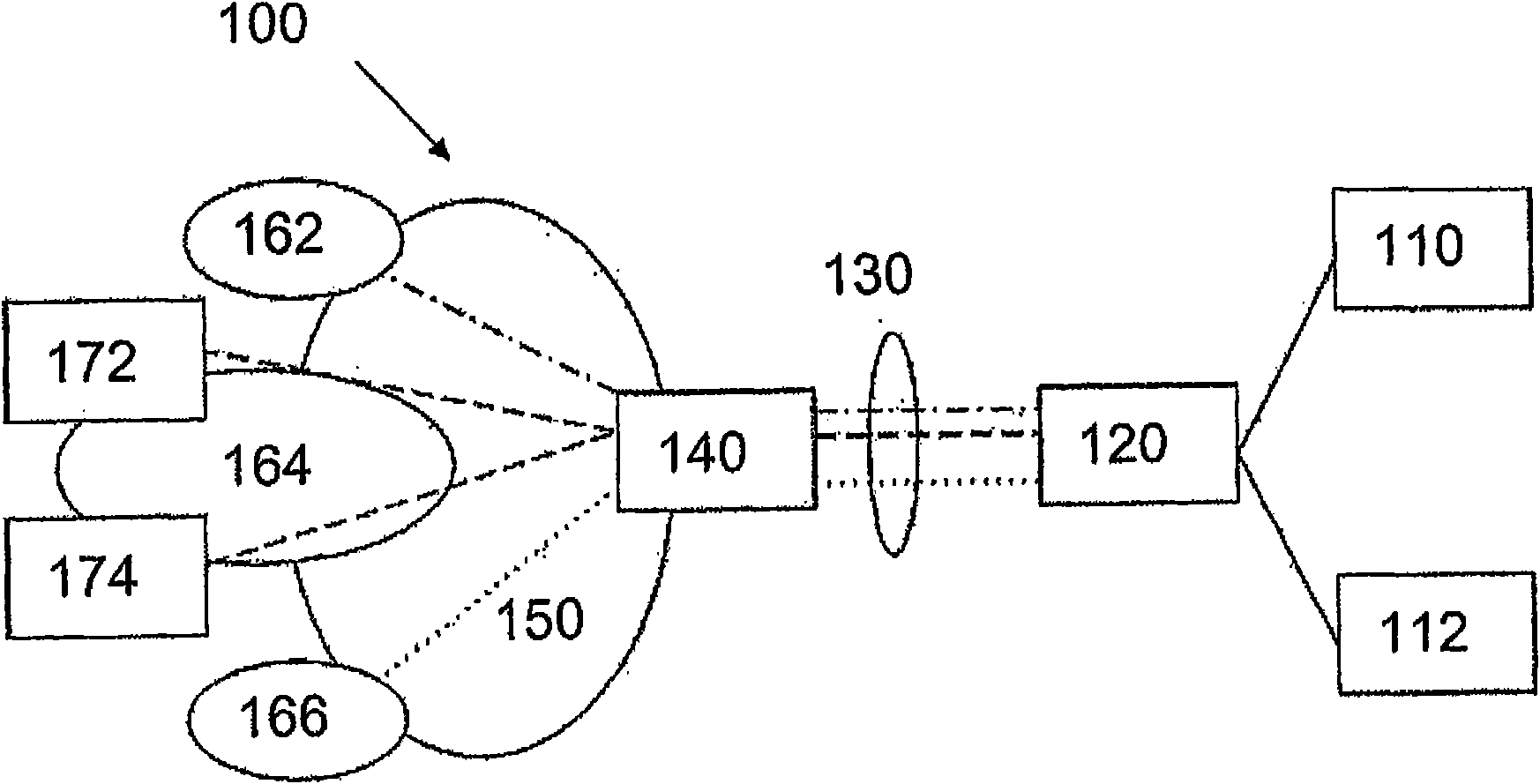
[0048] Figure 1 shows a network infrastructure 100 according to one embodiment of the present invention.

[0049] It should be mentioned here that the network infrastructure 100 in Figure 1 may represent any type of telecommunications network in which data is sent in packets or frames from end user hosts to nodes in the network. Thus, the invention can also be applied in wireless telecommunication networks which are part of the invention.

[0050] Now, the network infrastructure 100 in FIG. 1 comprises a first end user host 110 and a second end user host 112 connected to a learning bridge in case of an Ethernet connection. However, the first and second end-user hosts 110 , 112 may also be connected not to the learning bridge 120 but to an Ethernet switch, hub or some other Ethernet node performing a function equivalent to the learning bridge 120 . It should be mentioned here that the end user hosts 110 and 112 may include mobile terminals or static telecommunication terminals...


PUM


Abstract

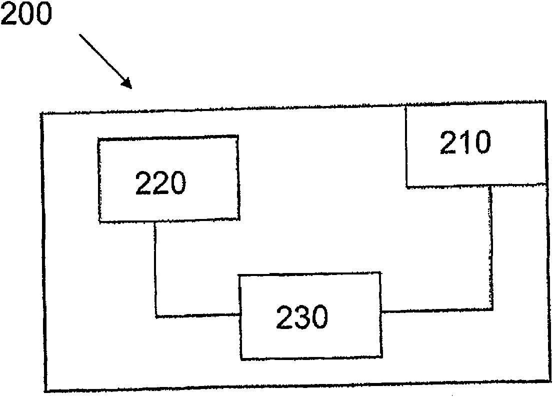
The present invention describes an access node (140, 200) for communication in a telecommunication network comprising: an input / output unit (210) adapted for receiving a first information message, wherein the first information message comprises a logical address associated with a virtual network node, a processing unit (230) for extracting the logical address of the virtual network node and for determining a hardware address associated with the logical address of the virtual network node, where the processing unit (230) is further adapted for a determining a logical address of an end-user host (110, 112 communicating with the virtual network node, wherein the access node (140) is configured to transmit a second information message comprising the logical and hardware address of the virtual network node to the logical address of the end-user host (110, 112). Also, a network infrastructure (100) where the access node (140, 200) is operating, is described. The access node (140, 200) also implements a method of the present invention by means of a computer program comprising instruction sets for implementing the method steps of the invention.

Description

technical field [0001] The invention relates to hardware address resolution in telecommunication networks. Background technique [0002] Typically, in today's telecommunications networks (of which the Internet is the most popular), data packets sent from one network entity to another have source and destination IP addresses, which in version 4 of the IP protocol are 4 byte length. However, the hardware network interfaces in these network entities do not understand the IP address format since they only operate using hardware addresses. Therefore, there is a need to find out the hardware address of a network entity to which another network entity sent one or more data packets. [0003] Since the most common type of hardware network interface is an Ethernet interface, these hardware addresses are most commonly MAC (Media Access Control) addresses using a 6-byte address format. A MAC address is typically assigned to a device after it is manufactured. [0004] Today, eg on th...

Claims


Application Information

Patent Timeline
IPC IPC(8): H04L29/12H04L12/56H04L45/586
CPCH04L12/66H04L29/12028H04L61/103H04L45/00H04L45/586H04L45/76
Inventor L·蒂姆T·梅尔森
Owner TELEFON AB LM ERICSSON (PUBL)
Learn More