
Computer system and base transceiver stations

a computer system and base transceiver technology, applied in the field of computer systems, can solve the problems of inability to reduce the number of times data must be stored in the database, and the data amount received by the business application server cannot be reduced, so as to achieve the effect of reducing the data amount received by the business application server

Inactive Publication Date: 2009-09-08
HITACHI LTD
View PDF8 Cites 2 Cited by
  • Summary
  • Abstract
  • Description
  • Claims
  • Application Information

AI Technical Summary

Benefits of technology

The invention is a sensor network system that reduces the amount of data received by a business application server. This is achieved by a computer system comprising wireless terminals, a business application server, and a base transceiver station. The base transceiver station manages the wireless terminals in groups and stores information received from them in a state history table. The system extracts difference information between the received information and the information stored in the state history table and sends it to the business application server. This reduces the data amount and the number of times data must be stored in the database.

Problems solved by technology

However, in the sensor network system described in JP-A No. 2004-32176, if the sensor node transmits only the node number to the business application server, the data amount received by the business application server cannot be reduced.
Also, the number of times data must be stored in the database cannot be reduced.

Method used


Image

  • Computer system and base transceiver stations
  • Computer system and base transceiver stations
  • Computer system and base transceiver stations

Examples


embodiment 1

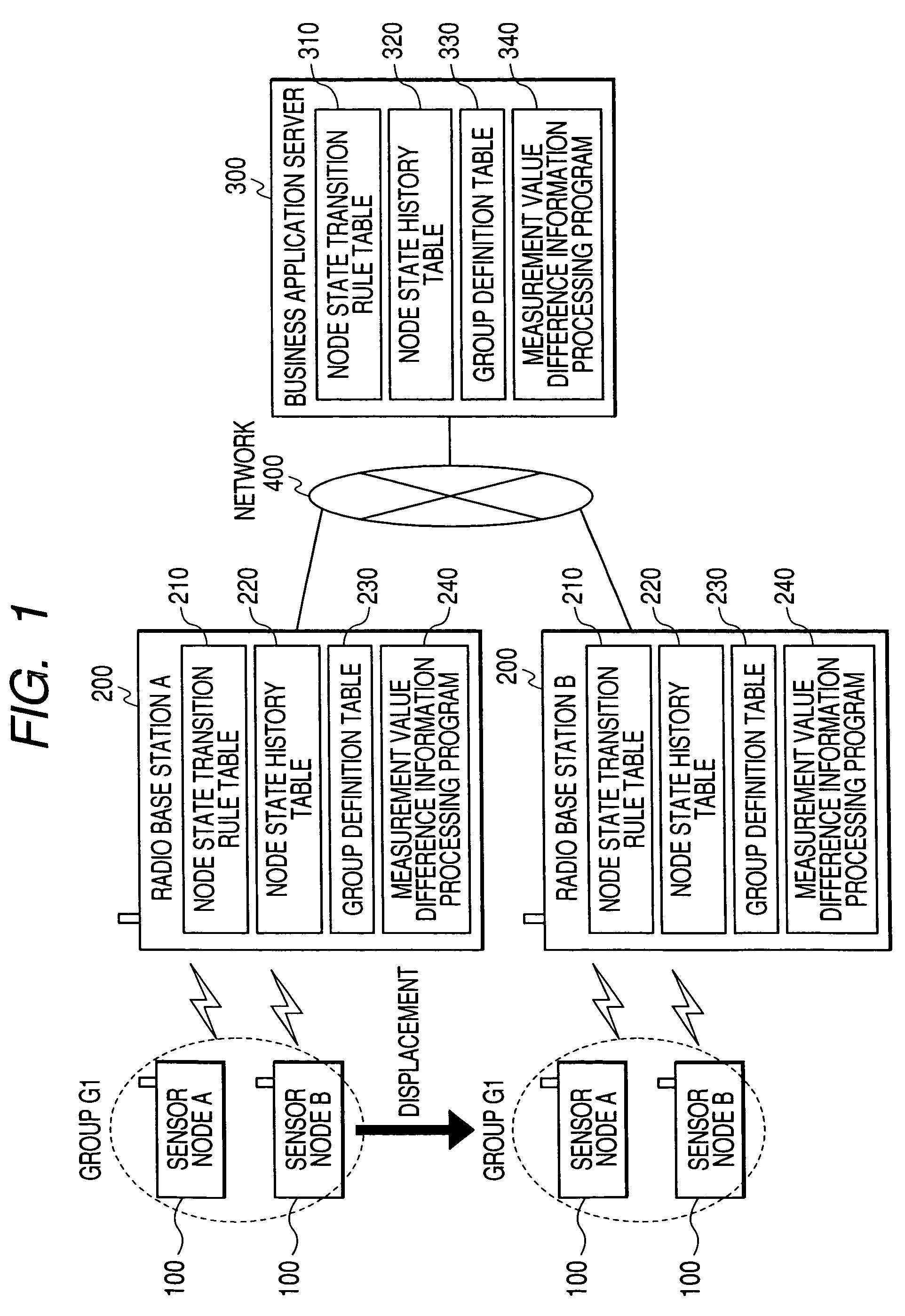
[0044]FIG. 1 is a block diagram of a sensor network system according to a first embodiment of the invention.

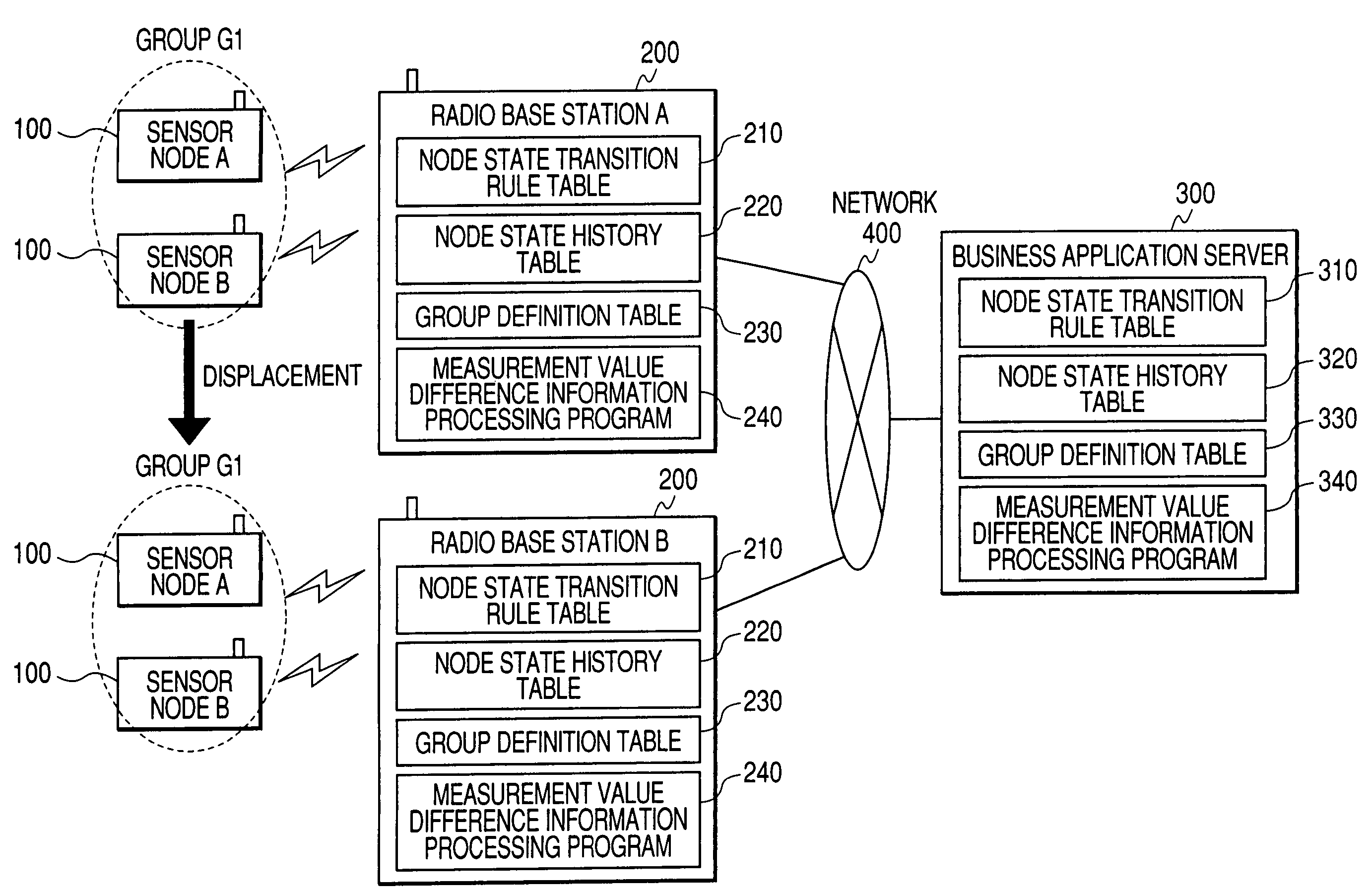
[0045]The sensor network system comprises a sensor node 100, base transceiver station 200, business application server 300 and network 400.

[0046]The sensor node 100 is an information processing terminal provided with a built-in sensor and wireless communications unit. The built-in sensor measures physical information. The wireless communications unit performs wireless communications with the base transceiver station 200.

[0047]The sensor node 100 measures various physical information using the built-in sensor, and the measured physical information (sensor data) is transmitted to the base transceiver station 200.

[0048]When a response request is received from the base transceiver station 200, the sensor node 100 of this embodiment transmits sensor data to the base transceiver station 200. The sensor node 100 may transmit the sensor data to the base transceiver station 200 with a ...

embodiment 2

[0378]In the second embodiment of the invention, the sensor node 100 measures the surrounding temperature by a sensor. The sensor node 100 then transmits sensor data including the measured temperature to the base transceiver station 200. The sensor node 100 may measure a physical quantity other than temperature.

[0379]Since the construction of the sensor network system of the second embodiment is identical to that of the sensor network system (FIG. 1) according to the first embodiment, its description will be omitted.

[0380]FIG. 12A is a schematic diagram of the group definition table 330 of the business application server 300 at the time T0 according to the second embodiment of the invention.

[0381]FIG. 12B is a schematic diagram of the group definition table 330 of the business application server 300 at the time T3 according to the second embodiment of the invention.

[0382]FIG. 12C is a schematic diagram of the group definition table 330 of the business application server 300 at the t...


PUM


Abstract

A computer system including wireless terminals which transmit information, a business application server which performs a predetermined operation based on information received from the wireless terminals, and a base transceiver station which relays communications between the wireless terminals and the business application server, are provided. The base transceiver station, to manage said plural wireless terminals in groups, stores a group definition table showing a correspondence between the wireless terminals and the groups, stores the information received from the terminals in a state history table which manages the state history of the wireless terminals, extracts difference information between the information received from the wireless terminals and the information stored in the state history table, summarizes the extracted difference information for each group, and transmits it to the business application server. The data amount received by a business application server is thus reduced.

Description

CLAIM OF PRIORITY[0001]The present application claims priority from Japanese Application JP 2005-22645 filed on Aug. 1, 2005, the content of which is hereby incorporated by reference into this application.FIELD OF THE INVENTION[0002]The present invention relates to a computer system comprising wireless terminals, base transceiver stations and a business application server, and in particular to a technique of reducing the data communication amount between these devices.BACKGROUND OF THE INVENTION[0003]A ubiquitous information society, which provides optimal data services according to the state or environment of things, is now becoming a reality. The use of ubiquitous information processing devices using IC chips such as smart cards or radio frequency tags (RFID) is also becoming more widespread. Trials of these devices in applied services like electronic banking, physical distribution management, security management or information services are now under way.[0004]In recent years, sen...

Claims


Application Information

Patent Timeline
Patent Type & Authority Patents(United States)
IPC IPC(8): H04W4/00H04W28/00
CPCH04L67/28H04L67/12H04L29/12132H04L61/1552H04L61/4552H04L67/56
Inventor MISHINA, YUSUKESATO, AKIKOMOTOBAYASHI, MASAHIRO
Owner HITACHI LTD
Learn More