Quick release pedal device without tool
A technology of pedals and tools, applied in transportation and packaging, vehicle parts, crank structures, etc., can solve the problems of complex device structure, unsuitable for industrialized mass production and application, and achieve environmental protection, size reduction, and lateral width reduction Effect
- Summary
- Abstract
- Description
- Claims
- Application Information
AI Technical Summary
Problems solved by technology
Method used
Image
Examples
no. 1 example
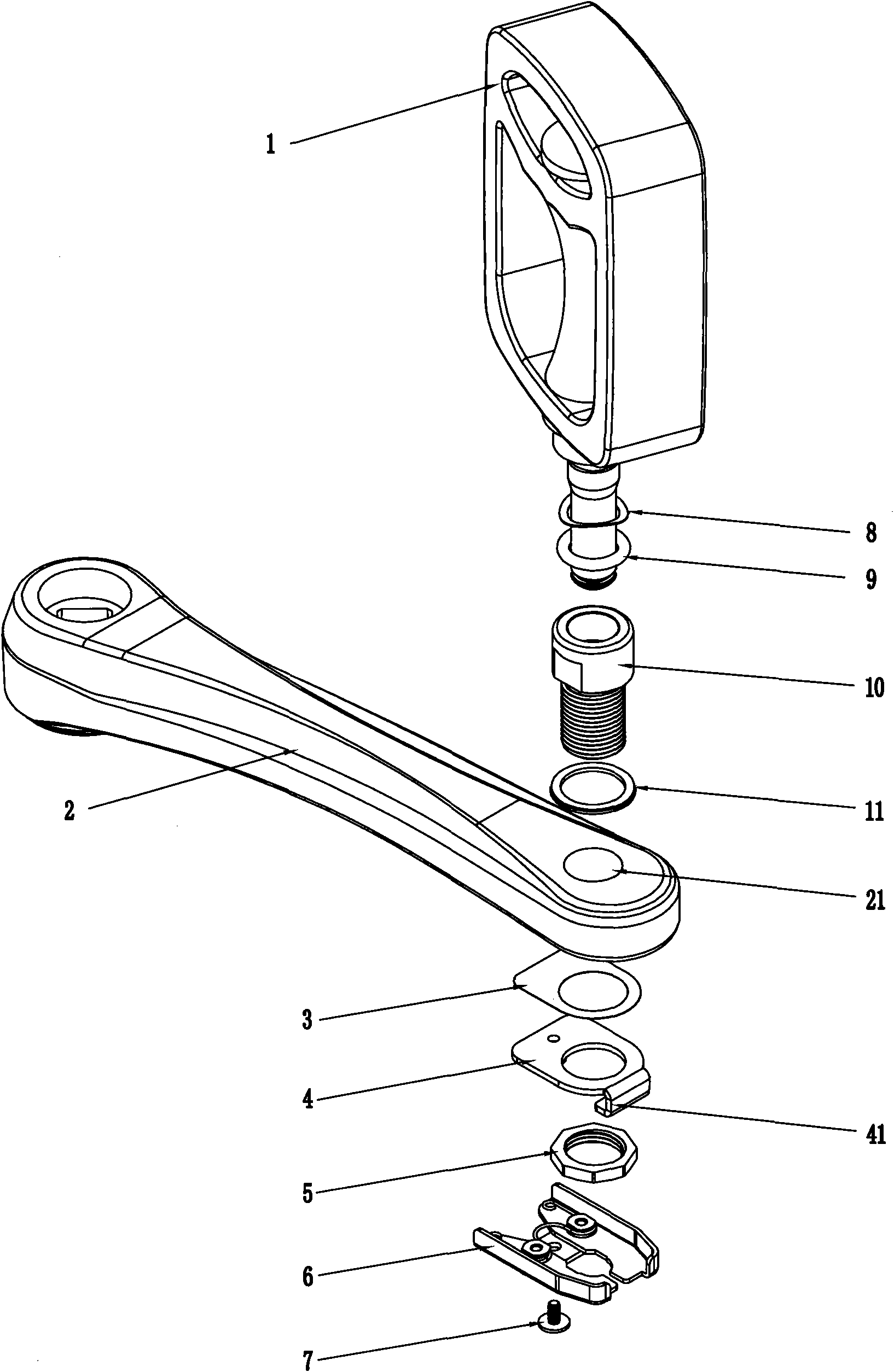
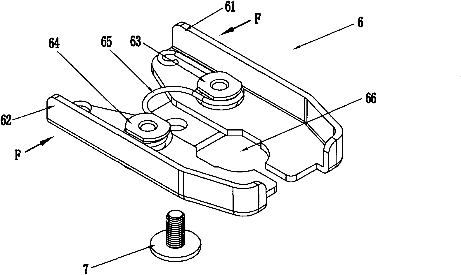
[0032] The first embodiment, such as figure 1 An adapter sleeve 10 is provided between the pedal 1 and the crank 2. The adapter sleeve 10 is a cylinder with a through hole on the inside, a boss is provided at the front section, and a thread is provided at the rear section. The thread and the crank threaded hole of the crank 2 21 to match. After the adapter sleeve is installed on the crank, its front end protrudes from the crank hole for a certain distance. The adapter sleeve 10 plus the adjusting gasket 11 is screwed into the crank hole, and the bracket plate 4 plus double-sided adhesive 3 is installed into the thread of the adapter sleeve from the inner side of the crank (the slot is downward) and is pressed and fitted on the crank by the compression nut 5 Inside, the compression nut 5 is screwed and fixed with the threaded part of the rear section of the adapter sleeve 10 passing through the crank hole 21 . Install the guillotine assembly 6 on the rear side of the bracket ...
no. 3 example
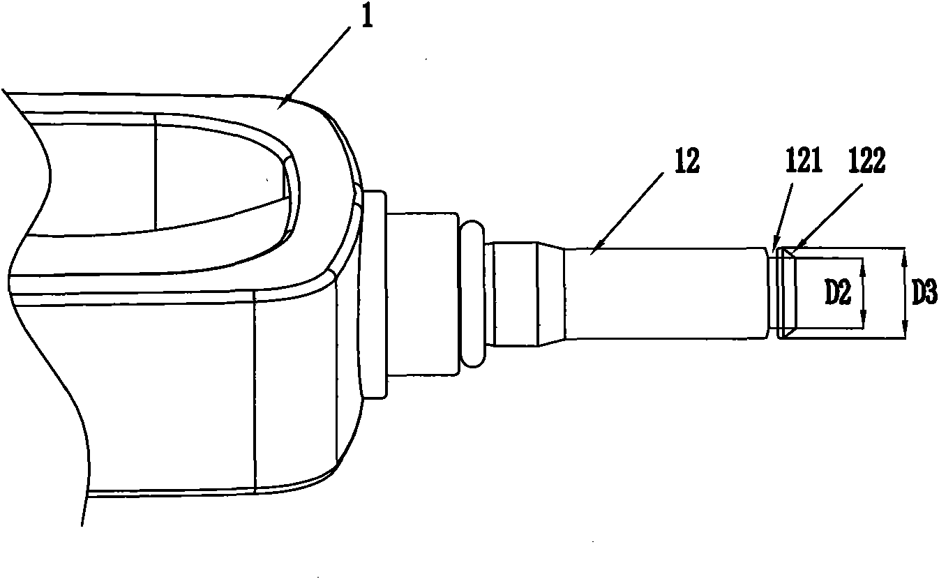
[0042] The third embodiment, such as Figure 9-10 , most of which are the same as in Embodiment 1, the difference is that the groove at the front end of the pedal shaft 12 is clamped from both sides by a torsion spring 504. on the inner end of the crank. A cover plate 501 may be provided outside the support plate and fixed by screws 502 . In this device, the torsion spring 504 has a certain elastic force. When there is no external force, the torsion spring 504 spontaneously closes to the middle, and under the external force when the pedal shaft is pushed into the crank, the torsion spring 504 is slightly separated and clamps the front end of the pedal shaft 12. Grooves for fixation.
[0043] Fourth embodiment, such as Figure 11 , the magnet adsorption type device, most of them are the same as the first embodiment, the difference is that the fixing method of the pedal shaft is different, in this program, the pedal shaft 12 does not need to be provided with a groove, and the...
no. 5 example
[0045] Fifth embodiment, such as Figure 12 , the front end of the pedal shaft 12 is provided with a groove, the lower end of the crank 2 is provided with a through hole 301, the through hole penetrates into the crank hole, a spring 302 is arranged in the through hole 301, a ball 303 is arranged at the front end of the spring, and the front end of the through hole 301 The diameter of the hole is smaller than that of the ball 303, so that the ball 303 is lifted upwards under the action of the spring force, and part of the ball 303 protrudes from the through hole 301, but cannot run out of the through hole. A screw 304 is provided at the lower end of the through hole 301 to limit the position of the spring. In this way, when the pedal shaft 12 is inserted into the crank hole by force, the ball 303 will withstand the groove of the pedal shaft 12 under the action of the spring force, and limit the left and right movement of the pedal shaft. And when the pedal shaft is to be disas...
PUM
 Abstract
Description
Claims
Application Information
 - R&D
- Intellectual Property
- Life Sciences
- Materials
- Tech Scout
- Unparalleled Data Quality
- Higher Quality Content
- 60% Fewer Hallucinations
Browse by: Latest US Patents, China's latest patents, Technical Efficacy Thesaurus, Application Domain, Technology Topic, Popular Technical Reports.
© 2025 PatSnap. All rights reserved.Legal|Privacy policy|Modern Slavery Act Transparency Statement|Sitemap|About US| Contact US: help@patsnap.com


