Electric door lock

A door lock, electric technology, applied in the field of locks, can solve the problems of complex internal structure, difficult automatic control, shortened service life of the door lock, etc., and achieve the effect of simple and reasonable structure, convenient operation and prolonging life

Inactive Publication Date: 2010-09-01
ZHEJIANG JULI INDAL TRADING
View PDF5 Cites 21 Cited by
  • Summary
  • Abstract
  • Description
  • Claims
  • Application Information

AI Technical Summary

Problems solved by technology

[0002] The most traditional door lock generally adopts the mechanical opening method of manual key. Although it is more reliable in use, it is more difficult to realize automatic control, and it is not as easy to change the opening and locking conditions as electric door locks; Through infrared, fingerprint, swiping card, password and other identification, the logic circuit controls the rotation of the motor to drive the lock tongue to open and lock. However, due to the high reliability of mechanical locks and has been recognized and trusted by consumers, many electric door locks often The mechanism lock structure that is opened and locked by the key is still retained, not only for the purpose of insurance after the electric opening and locking fail, but also to cater to people who are accustomed to traditional mechanical opening and locking; for example, Chinese patent 03250334. "Lock" discloses an electric lock, which is driven by a compound drive gear. Not only is its internal structure relatively complicated and unreasonable, but also the mechanical opening and locking methods are not independent from the electric opening and locking methods. Electric opening and locking require It can only be realized through the deceleration device and the compound drive gear, and the mechanical opening and locking also need to drive the deceleration device and the compound drive gear to realize it, which is relatively difficult, the key is laborious to turn, and the service life of the door lock is greatly shortened; The latch bolt is two completely independent systems and the latch bolt can be opened at any time. The latch bolt has no positioning function, which brings a lot of inconvenience to the user and affects the service life of the lock.

Method used


Image

  • Electric door lock
  • Electric door lock
  • Electric door lock

Examples


Embodiment Construction

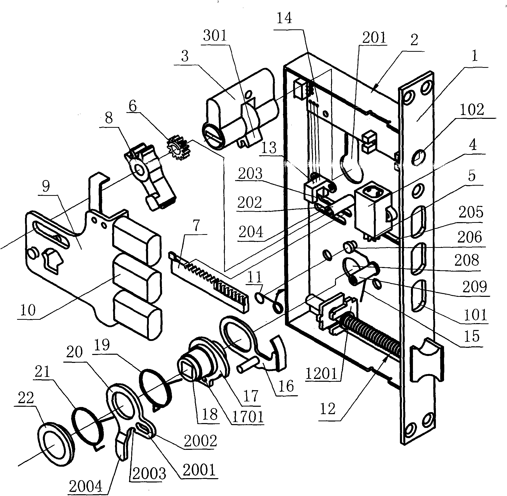
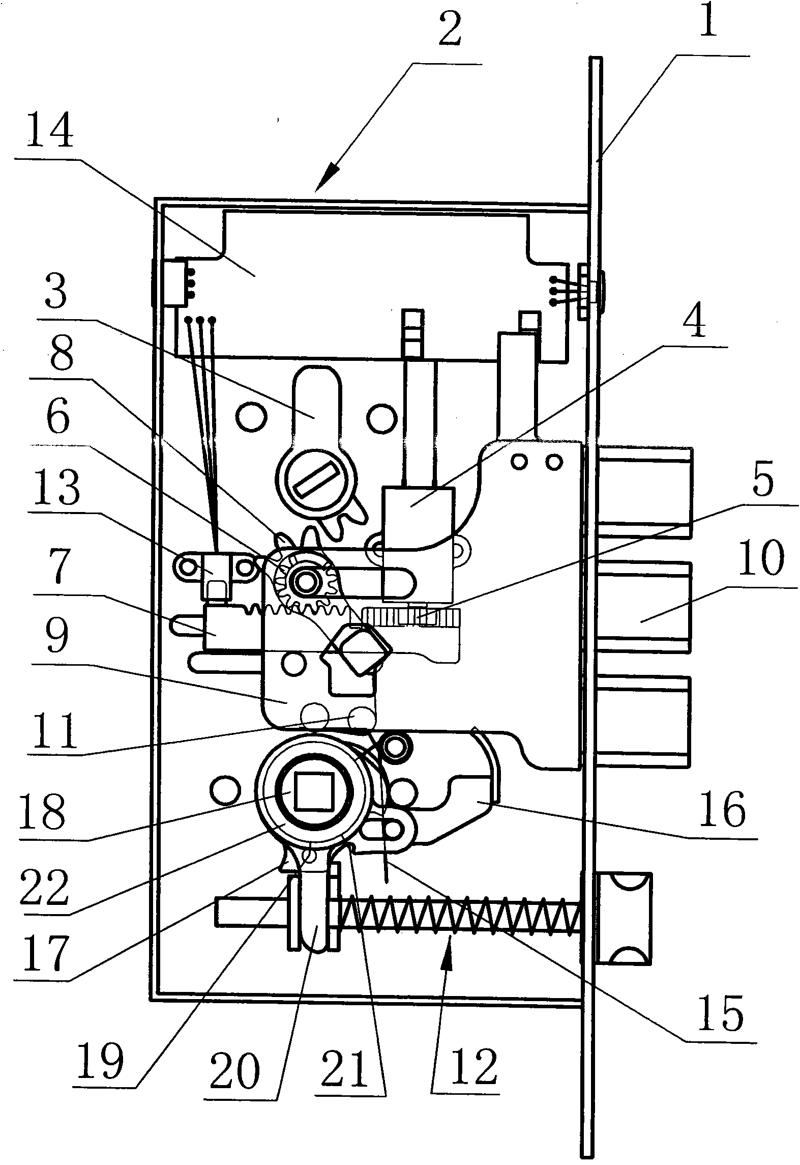
[0033]The technical solution that the present invention can adopt to solve the above-mentioned technical problems is: the electric door lock includes a lock box 2, a side panel 1, a main bolt 10, a bolt assembly 12, a bolt shift fork 20, a motor 4, and a drag plate 9 , lock cylinder 3 and circuit board 14 etc., circuit board can comprise the logic circuit of sensor, identification sensor signal and unlocking signal etc., the drive circuit of control motor rotation (comprising forward or reverse), sensor can use commercially available product , logic circuit and drive circuit can adopt existing mature circuit to make some settings, and its characteristic is: also be provided with the transmission mechanism that transfers the motor rotation action and cooperates with main deadbolt shift fork 8, and transmission mechanism can comprise main gear 5 , tooth piece 7, toggle gear 6, main dead bolt shift fork 8, main dead bolt shift fork torsion spring 11, described motor 4 is fixed on ...


PUM


Abstract

The invention belongs to the technical field of lockset and particularly relates to an electric door lock. The electric door lock comprises a side panel (1), a lock box (2), a main bolt (10), a carriage (9), a main bolt shifting fork (8), a latch bolt assembly (12), a lock core (3), a motor (4) and a circuit board (14), wherein the carriage (9) is connected with the main bolt (10); the main bolt shifting fork (8) drives the main bolt (10) to act through the carriage (9); and the rotating action of the lock core (3) or the motor (4) acts on the carriage through the main bolt shifting fork to drive the main bolt (10). The electric door lock is characterized in that: the motor (4) acts on the main bolt shifting fork through a transmission mechanism; and a joint action between the transmission mechanism and the main bolt shifting fork is provided with a free travel, so the lock core pulls the main bolt shifting fork within a free travel action range and the main bolt extends out of the side panel to lock or retracts to the side panel to unlock.

Description

technical field [0001] The invention belongs to the technical field of locks, and in particular relates to an electric door lock. Background technique [0002] The most traditional door lock generally adopts the mechanical opening method of manual key. Although it is more reliable in use, it is more difficult to realize automatic control, and it is not as easy to change the opening and locking conditions as electric door locks; Through infrared, fingerprint, swiping card, password and other identifications, the logic circuit controls the rotation of the motor to drive the lock tongue to open and lock. However, due to the high reliability of mechanical locks and has been recognized and trusted by consumers, many electric door locks are often used. The mechanism lock structure that is opened and locked by the key is still retained, which is not only for the purpose of insurance after the electric opening and locking fail, but also to cater to people who are accustomed to tradi...

Claims


Application Information

Patent Timeline
Patent Type & Authority Applications(China)
IPC IPC(8): E05B47/06E05B59/04
Inventor 应赤
Owner ZHEJIANG JULI INDAL TRADING
Why Eureka
Try Eureka