Suction nozzle structure with light source

A technology of light source and light source gun, which is applied to parts, instruments, and measuring devices of electrical measuring instruments, can solve problems such as inability to test products, and achieve the effects of saving test time and improving test efficiency

Inactive Publication Date: 2010-09-01
BYD CO LTD
View PDF4 Cites 5 Cited by
  • Summary
  • Abstract
  • Description
  • Claims
  • Application Information

AI Technical Summary

Problems solved by technology

[0003] The purpose of the present invention is to provide a suction nozzle structure with a light source, which aims to solve the problem that the suctio

Method used


Image

  • Suction nozzle structure with light source
  • Suction nozzle structure with light source
  • Suction nozzle structure with light source

Examples


Embodiment Construction

[0018] In order to make the object, technical solution and advantages of the present invention clearer, the present invention will be further described in detail below in conjunction with the accompanying drawings and embodiments. It should be understood that the specific embodiments described here are only used to explain the present invention, not to limit the present invention.

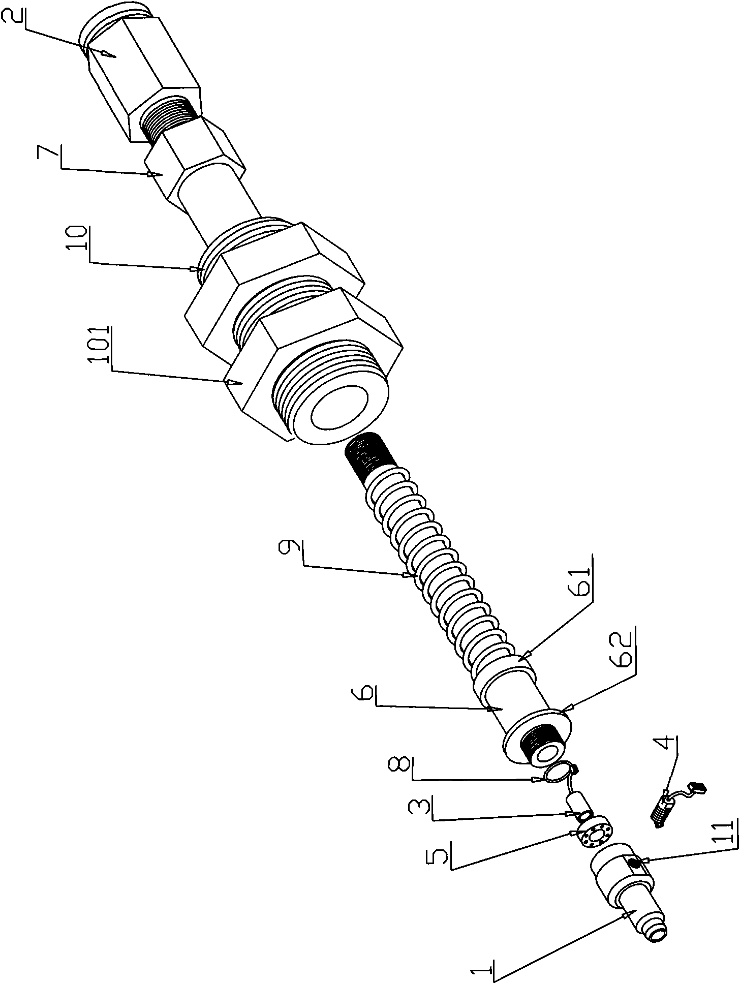
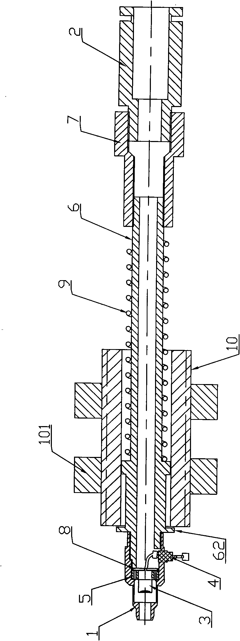
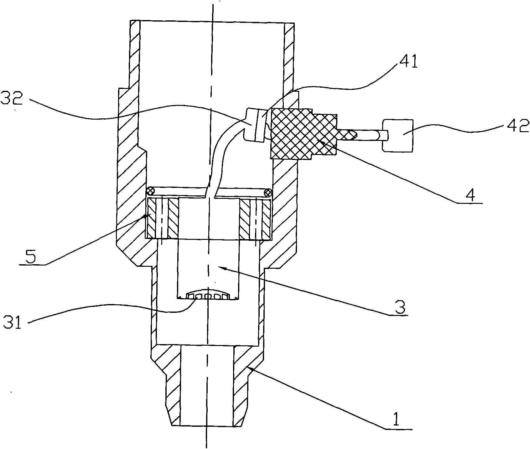
[0019] refer to Figure 1 to Figure 8 As shown, a suction nozzle structure with a light source provided by the embodiment of the present invention includes a suction nozzle 1 and a trachea joint 2 connected to the suction nozzle 1, and the trachea joint 2 is connected to a suction device (not shown in the figure) Out) connection, also includes a light source gun 3 arranged in the suction nozzle 1, the light source gun 3 is connected with a light source signal connection block 4.

[0020] Specifically, the suction nozzle 1 is cylindrical, and its inner surface needs to be surface treated to make it...


PUM


Abstract

The invention is suitable for the technical field of suction nozzles and provides a suction nozzle structure with a light source. The structure comprises a suction nozzle, an air pipe connector and a light source gun, wherein the air pipe connector is connected with the suction nozzle and air suction equipment; and the light source gun is arranged in the suction nozzle and connected with a light source signal connection block. Through the suction nozzle structure with the light source provided by the invention, a plurality of tests can be performed at the same time when the suction nozzle adsorbs products to a test position by arranging the light source gun which can transmitting the light source in the suction nozzle, so that the problem that the products are tested by adsorbing the products to different test positions respectively is solved; the test time is saved; and the testing efficiency is improved.

Description

technical field [0001] The invention belongs to the technical field of suction nozzles, in particular to a suction nozzle structure with a light source. Background technique [0002] After the suction nozzle in the prior art is connected to the suction device, when the suction device is working, the suction nozzle can absorb the product, so that the product can be adsorbed to a corresponding position for related testing. However, this kind of suction nozzle has a single function and only has the function of adsorption. When testing the product, it is necessary to adsorb the product to different test positions to complete the test of the product. For example, in the electrical performance test of the CMOS image sensor chip When the image and sensitivity test cannot be performed at the same time, the chip needs to be adsorbed to the image test position and the sensitivity test position for testing after the electrical performance test, which wastes test time and is very ineffi...

Claims


Application Information

Patent Timeline
IPC IPC(8): G01R1/02G01R31/28
Inventor 黄镇生李立董志敏
Owner BYD CO LTD
Why Eureka
Try Eureka