Blade stirring type pneumatic conveyor for easy caking materials

A pneumatic conveying and agitating technology, which is applied in the field of blade agitating pneumatic conveying devices, can solve the problems of low pressure resistance of equipment, limited conveying distance, easy loss of moving parts, etc., and achieve the effects of reliable operation, energy saving and strong practicability

Inactive Publication Date: 2010-09-08
杭州震乾科技有限公司
View PDF4 Cites 13 Cited by
  • Summary
  • Abstract
  • Description
  • Claims
  • Application Information

AI Technical Summary

Problems solved by technology

Some of the materials are in the form of dispersed powder when the temperature is high. However, during the transportation and packaging process, due to the decrease in temperature, they will stick and agglomerate, which cannot be handled by conventional pneumatic conveying and feeding equipment.
At present, the co

Method used


Image

  • Blade stirring type pneumatic conveyor for easy caking materials
  • Blade stirring type pneumatic conveyor for easy caking materials

Examples


Embodiment 1

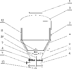
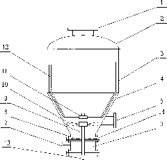
[0013] As attached to the manual figure 1 As shown, a blade-stirring pneumatic conveying device for materials that are easy to agglomerate. The hollow pump body is formed by the upper oval head 2, the middle cylindrical body 3 and the lower conical head 4. There is a feed port 1 on the oval head 2. There is a discharge port on the conical head 4 and a fluidization chamber 6 on the bottom of the conical head 4 . The conical head 4 is connected to the fluidization chamber 6 with flanges 14, and there is a fluidization device 8 between the flanges 14. The fluidization chamber has an air inlet 7. A scraper 12 and a blade 10 are arranged inside the pump body, and the scraper 12 and the blade 10 are fixed on the aerodynamic structure 11 of the fixed shaft 9, and the air inlet 13 connected to the other end of the fixed shaft extends out of the pump. The fixed shaft 9 is a hollow circular tube. Compressed gas enters from the inside of the fixed shaft 4 and blows out through the pn...


PUM


Abstract

The invention relates to pneumatic conveyor, in particular to a blade stirring type pneumatic conveyor for easy caking materials. The blade stirring type pneumatic conveyor for the caking materials comprises a bilge pump, a feeding hole and a discharge hole, wherein the feeding hole and the discharge hole are both arranged on the bilge pump, and the bilge pump consists of an oval seal head at the top, a columniform cylinder at the middle and a conical seal head at the bottom. The blade stirring type pneumatic conveyor is characterized in that a scraper and a pneumatic blade are arranged inside the bilge pump and are fixed on a pneumatic structure at the top of a fixed shaft, the fixed shaft is a hollow circular tube, and the other end of the fixed shaft is connected with an air inlet extending out of the bilge pump. The invention has the characteristics of capability of effectively crushing the caking materials, reliable work, energy source saving, simple and convenient operation, strong practicability and the like.

Description

technical field [0001] The invention relates to a pneumatic conveying device, in particular to a blade-stirred pneumatic conveying device for easily agglomerated materials. Background technique [0002] As we all know, with the rapid development of new material science and technology in recent years, in the chemical industry, chemical fiber, food, pharmaceutical and other industries, a large number of new materials with different properties have been produced through the research and development of new technologies and new processes. Some of the materials are in the form of dispersed powder when the temperature is high. However, during the transportation and packaging process, due to the decrease in temperature, they will stick and agglomerate, which cannot be handled by conventional pneumatic conveying and feeding equipment. At present, the transportation is generally carried out continuously by screw plunger pumps. Not only are the moving parts prone to wear and tear, but ...

Claims


Application Information

Patent Timeline
IPC IPC(8): B65D88/68B65D88/72
Inventor 言侃黄韬
Owner 杭州震乾科技有限公司
Why Eureka
Try Eureka