Reentrant interference optical fiber gyroscope

A technology of fiber optic gyroscope and fiber optic pair, which is applied in the direction of Sagnac effect gyroscope, etc., can solve the problem that the long path of the effective ring is not greatly improved.

Inactive Publication Date: 2010-09-08
PEKING UNIV
View PDF4 Cites 28 Cited by
  • Summary
  • Abstract
  • Description
  • Claims
  • Application Information

AI Technical Summary

Problems solved by technology

In order to solve this problem, the researchers proposed a passive re-entrant fiber optic gyroscope, but because it uses a common coupler, the effective loop long path does not improve much

Method used


Image

  • Reentrant interference optical fiber gyroscope
  • Reentrant interference optical fiber gyroscope
  • Reentrant interference optical fiber gyroscope

Examples


Embodiment Construction

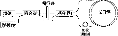
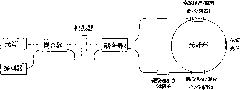
[0061] ASE wide-spectrum light source is used, the center wavelength is 1550nm, and the bandwidth is about 50nm. After passing through the 3db2×2 coupler 1, it is polarized to the fast axis by the polarizer. After passing through a 3db2×2 polarization-maintaining coupler 2, it is divided into two beams of light propagating on the fast axis with equal power. A lithium niobate phase modulator is connected to one of the branch optical paths. The polarization-maintaining pigtail at the output end of the polarization-maintaining coupler 2 should be fused axially with the polarization-maintaining branch of the polarization-maintaining / rotating combiner / beam splitter. The combined pigtail of the polarization maintaining / rotating combiner / splitter can be spliced ​​with the polarization maintaining fiber ring on the axis. In the center of the fiber ring, a certain rotation angle such as 5° is fused with a short section of polarization-maintaining fiber, and then the polarization-main...


PUM


Abstract

The invention discloses a reentrant interference optical fiber gyroscope, belonging to the field of optical fiber communication. The reentrant interference optical fiber gyroscope comprises a broadband source, a 2X2 coupler, a polarizer, a detector, a 2X2 polarization-maintaining coupler, a phase modulator, two polarization-maintaining/rotary beam combining/ splitting devices and a polarization-maintaining optical fiber ring, wherein one port of the 2X2 polarization-maintaining coupler is connected with a beam splitting port of one polarization-maintaining/rotary beam combining/ splitting device, and the other port of the 2X2 polarization-maintaining coupler is connected with the beam splitting port of the other polarization-maintaining/rotary beam combining/ splitting device through the phase modulator; the beam combining ports of the two polarization-maintaining/rotary beam combining/ splitting devices are respectively connected with the two ports of the polarization-maintaining optical fiber ring; a polarization-maintaining optical fiber segment is connected in the polarization optical fiber ring, and a set angle is arranged between the fast and slow axis of the polarization-maintaining optical fiber segment and the fast and slow axis of the polarization-maintaining optical fiber; and the other beam splitting ports of the two polarization-maintaining/rotary beam combining/ splitting devices are connected through optical fibers. The invention reduces the cost of the optical fiber gyroscope and improves the measurement precision of the speed of the angle of rotation.

Description

technical field [0001] The invention relates to a fiber optic gyroscope, in particular to a reentrant interference type fiber optic gyroscope, which belongs to the field of fiber optic communication. Background technique [0002] A gyroscope is a device that can detect relative space rotation with high precision. There are many types of gyroscopes that use the physical effects of rotation to study, such as mechanical gyroscopes, fiber optic gyroscopes, and atomic gyroscopes. The fiber optic gyroscope is an all-solid-state inertial device with simple structure, low cost and high precision. It has a wide range of applications in military and civilian fields, such as tactical weapon guidance, aerospace directional navigation, car navigation, robot control, etc. [0003] The basic principle of the fiber optic gyroscope is based on the Sagnac effect, which is a relativistic effect. Simply put, in a closed optical loop of arbitrary shape, starting from any point in the loop, the...

Claims


Application Information

Patent Timeline
Patent Type & Authority Applications(China)
IPC IPC(8): G01C19/72
Inventor 王玉杰李正斌
Owner PEKING UNIV
Why Eureka
Try Eureka