

Liquid crystal display device and processing method of digital image signal
A liquid crystal display device, digital image technology, applied in identification devices, static indicators, instruments, etc., can solve problems such as unfavorable implementation, low backlight brightness, loss of image details, etc., to avoid image contrast reduction, expand image range, and easily The effect of hardware implementation
- Summary
- Abstract
- Description
- Claims
- Application Information
AI Technical Summary
Problems solved by technology
Method used
Image

Examples
Embodiment 1
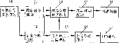
[0066] This embodiment provides a liquid crystal display device, such as figure 1 As shown, it includes: a liquid crystal drive module 15, a backlight drive module 16, a liquid crystal panel 18 and an LED backlight 17, an image signal receiving module 10, an image cache module 11, an image analysis module 12, a backlight brightness calculation module 13, and a liquid crystal gray scale calculation module 15. Image signal receiving module 10 is connected with image cache module 11, image analysis module 12 respectively, is used to provide digital image signal to image cache module 11 and image analysis module 12; Image cache module 11 is connected with liquid crystal gray scale calculation module 14, Used to receive and buffer digital image signals for use by the liquid crystal grayscale calculation module 14 to adjust the liquid crystal grayscale; the image analysis module 12 is connected to the backlight brightness calculation module 13 for receiving digital image signals and...
Embodiment 2
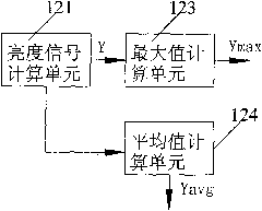
[0068] On the basis of Example 1, such as figure 2 As shown, preferably, in this embodiment, a brightness signal calculation unit 121, an average value calculation unit 124, and a maximum value calculation unit 123 are set in the image analysis module, and the brightness signal calculation unit 121 is used to receive the digital image signal, Calculate the image brightness signal according to the formula Y=0.299×R+0.587×G+0.114×B, wherein Y is the image brightness signal, R, G, and B are the original grayscale data of the digital image signal, and the average value calculation unit 124 is connected with the luminance signal calculation unit 121 for calculating the average value Yavg of the image luminance signal, and the maximum value calculation unit 123 is connected with the luminance signal calculation unit 121 for calculating the value of the image luminance signal Maximum value Ymax.
Embodiment 3
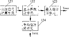
[0070] On the basis of Example 1, such as image 3 As shown, preferably, the present embodiment further sets a histogram statistical unit 121 in the image analysis module 12, and its connection relationship is changed to: the luminance signal calculation unit 121 and the histogram statistic unit 122 are connected in sequence, and the luminance signal calculation unit 121 It is used to receive the digital image signal, calculate the image brightness signal according to the formula Y=0.299×R+0.587×G+0.114×B, where Y is the image brightness signal, R, G, B are the original grayscale data of the digital image signal, the histogram Figure statistics unit 122 is used for carrying out histogram statistics to image luminance signal Y, and histogram statistics unit 122 is also connected with average value calculation unit 124 and maximum value calculation unit 123 respectively, and average value calculation unit 124 is used for according to histogram statistics unit 122 Calculate the a...
PUM
 Abstract
Description
Claims
Application Information