Variable gain amplifier for linearity optimization at low gain

A gain amplifier, linearity technology, used in DC coupled DC amplifiers, differential amplifiers, improved amplifiers to reduce nonlinear distortion and other directions, can solve problems such as gain compression and nonlinearity

Inactive Publication Date: 2010-09-08
FUDAN UNIV
View PDF4 Cites 24 Cited by
  • Summary
  • Abstract
  • Description
  • Claims
  • Application Information

AI Technical Summary

Problems solved by technology

Therefore, when the VGA has a small gain, it generally processes large signals. If the problem of the limitation of the signal swing when the VGA is processed with a small gain is not solved, placing a large signal at the input of the VGA will inevitably lead to very serious problems. Non-linear, the gain is bound to be heavily compressed

Method used


Image

  • Variable gain amplifier for linearity optimization at low gain
  • Variable gain amplifier for linearity optimization at low gain
  • Variable gain amplifier for linearity optimization at low gain

Examples


Embodiment Construction

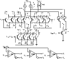
[0036] The specifically designed circuit parameters of the VGA structure of the present invention are as Figure 5 As shown, the practice is carried out under the TSMC 0.13um process, and the simulation tool is Cadence SpectreRF. against Figure 5 In the experimental circuit shown, keep the input signal amplitude and circuit gain unchanged, change the digital control signal, observe the output signal amplitude and the third-order harmonic, and the input signal frequency is 1MHz. The experimental results are shown in Table 1.

[0037] Table 1 Comparison of experimental results

[0038] D. 2 D. 1 D. 0

[0039] Figure 6 , Figure 7 and Figure 8 The VGA amplitude-frequency response curves, transient waveforms, and spectrum analysis in the cases of 000 and 111 respectively, the data have been summarized in Table 1. It can be seen from Table 1 that as the effective current of the current bias array increases, the linearity of the circuit is significantly impr...


PUM


Abstract

The invention discloses a variable gain amplifier (VGA) for linearity optimization at low gain, belonging to the technical field of analogue integrated circuits. The variable gain amplifier adopts pseudo-indexes to approximately realize linear variation by decibel. The variable gain amplifier is formed by a variable transconductance array, a bias current array, a digital control circuit, a transistor variable load connected with a diode, and a common-mode feedback circuit. The VGA realizes the variable gain of the VGA through changing the bias current of the variable transconductance and the variable load and realizes the linearity optimization when the gain of the VGA is low. Since the bias current of the variable transconductance array is very small at low gain, the variation of the width-to-length ratio effective value of the variable transconductance array does not have great impacts on the overall power consumption of the VGA. A circuit structure can be realized by using a CMOS technology.

Description

technical field [0001] The invention belongs to the technical field of analog integrated circuits, and in particular relates to the design of a variable gain amplifier (variable gain amplifier, VGA) whose linearity is optimized at low gain. It can be used as the analog baseband back end of the wireless communication receiver and the pre-drive amplifier of the analog-to-digital converter. Background technique [0002] The VGA is located at the analog back end of a wireless communication receiver, and combined with an automatic gain control system, it can increase or decrease the received signal power to match the driving analog-to-digital converter. Compared with the discretely adjustable programmable gain amplifier (programmable gain amplifier, PGA), a significant advantage of the analog signal-controlled VGA is that it can continuously adjust the gain change, that is, its gain step size can be infinitely small, which is very important for improving wireless communication re...

Claims


Application Information

Patent Timeline
Patent Type & Authority Applications(China)
IPC IPC(8): H03F1/32H03F3/45
Inventor 李巍樊锦涵高亭李宁任俊彦
Owner FUDAN UNIV
Why Eureka
Try Eureka