
Combine

A combine harvester and engine technology, applied to harvesters, steering mechanisms, guiding agricultural machinery, etc., can solve the problems of high cost of parts, inability to simply form a gearbox, troublesome operation, etc., achieve small size and light weight, and realize light Quantitative, easy-to-maintain effect

Inactive Publication Date: 2010-09-08
YANMAR POWER TECHNOLOGY CO LTD
View PDF5 Cites 8 Cited by
  • Summary
  • Abstract
  • Description
  • Claims
  • Application Information

AI Technical Summary

Problems solved by technology

[0007] However, in the combine harvester of Patent Document 1, long rods, arms, pivot pins, etc. are often used in the mechanical linkage mechanism, and since it is a rather complicated structure, the cost of parts required in the mechanical linkage mechanism is high. , not commensurate with the cost reduction requirements that have risen in recent years
[0008] Moreover, in the combine harvester of Patent Document 1, since the travel body is turned only by the operation of the manual operation member for turning, even if it is easy to turn a large amount, when moving along the row of uncut grain stalks on the farm, the It is also very troublesome to operate the manual operation parts for the rotation
In order to carry out the line and line combination operation of turning the traveling body along the row of uncut grain stalks on the farm, an actuator configured to make the rotary transmission perform a rotary operation is provided, but since the actuator is arranged in the gearbox, it has Can not simply constitute a gearbox and other issues

Method used


Image

  • Combine
  • Combine
  • Combine

Examples


Embodiment Construction

[0090] Hereinafter, embodiments embodying the invention of the present application will be described with reference to the drawings.

[0091] (1), the general structure of the combine harvester

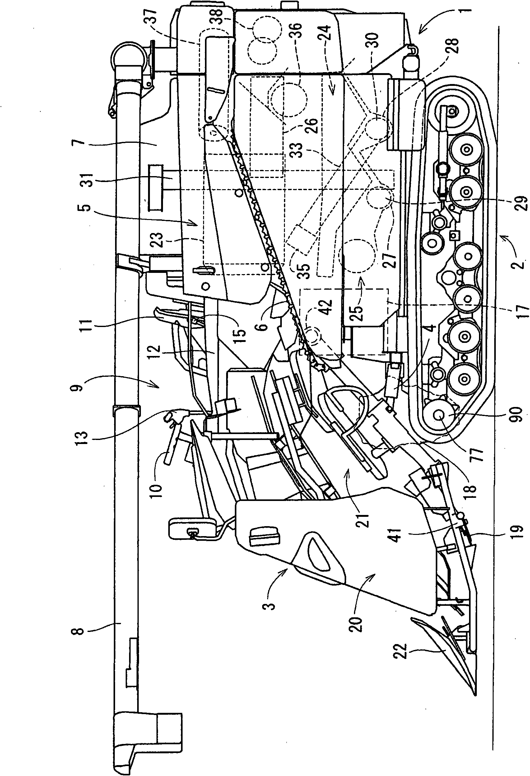
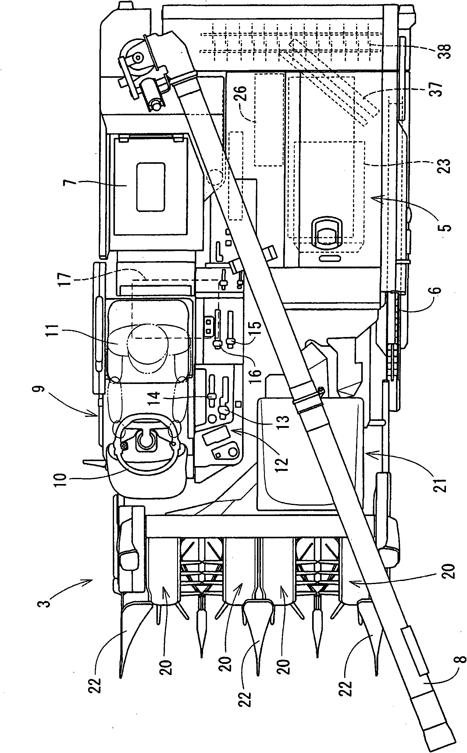
[0092] First, refer to figure 1 and figure 2 The schematic structure of a combine harvester is demonstrated.

[0093] A combine harvester which is an example of a traveling vehicle is equipped with the traveling body 1 supported by the left-right pair of traveling crawler belt 2 which is a traveling part. The front portion of the traveling body 1 is equipped with a harvesting device 3 that can be adjusted up and down by a single-acting hydraulic cylinder 4 to harvest the grain stalks (uncut grain stalks) of the farm while harvesting.

[0094] The threshing apparatus 5 with the feed chain 6, and the grain box 7 which store|stores the grain after threshing are mounted side by side on the traveling body 1. As shown in FIG. In this case, the threshing apparatus 5 is arrange|positione...


PUM


Abstract

Disclosed is a running vehicle comprising a straight drive transmission (53) for transmitting the power of an engine (17) to the left and right running sections (2) and a turning transmission (54) for transmitting the engine power to the left and right running sections while reversing rotation, a straight drive manual operation tool (13) of the straight drive transmission (53), and a turning manual operation tool (10) of the turning transmission, wherein the turning operation mechanism is simplified while turning operation performance is enhanced. A control body (131) rotatable about two axes (P, S) intersecting perpendicularly is provided, and the control body controls the turning transmission to perform turning operation through a turning interlock mechanism (180) by forward / reverse rotation about the first axis (P) caused by the turning operation of the turning manual operation tool, and controls the straight drive transmission to perform a speed change operation by forward / reverse rotation about the second axis (S) caused by the speed change operation of the straight drive manual operation tool, wherein the turning interlock mechanism is equipped with a hydraulic cylinder (193) for operating the turning transmission to turn.

Description

technical field [0001] The present invention relates to a combine harvester equipped with a reaping device and a threshing device, and more specifically relates to a combine harvester for continuously harvesting grains by steering and operating a traveling body to move along uncut grain stalk rows in a farm. Background technique [0002] Conventionally, in a combine harvester, power from an engine mounted on a traveling body is transmitted through a transmission for straight travel, and at the same time, a transmission for turning reversely rotates and transmits power to traveling parts such as crawler belts for left and right travel. [0003] An example of the combine harvester of such a structure is disclosed by patent document 1. In the combine harvester of patent document 1, the drive output amount of the transmission for straight travel, ie, the straight travel speed of a traveling body is adjusted by the operation amount of the manual operation elements for straight tr...

Claims


Application Information

Patent Timeline
IPC IPC(8): A01B69/00A01D69/00B62D11/08B62D11/18
CPCB62D11/18B62D11/006A01D69/00
Inventor 桐畑俊纪
Owner YANMAR POWER TECHNOLOGY CO LTD
Learn More