Shock absorbing mechanism of open/close moving element and drawing device employing it

A technology of buffer mechanism and moving body, applied in the field of buffer mechanism, can solve problems such as loosening of gears on both sides, tooth defect and bounce of both gears, etc., and achieve the effects of suppressing impact, simple structure, and smooth power transmission

Inactive Publication Date: 2010-09-08
KYOEI KANAMONO SEISAKUSHO +1
View PDF6 Cites 5 Cited by
  • Summary
  • Abstract
  • Description
  • Claims
  • Application Information

AI Technical Summary

Problems solved by technology

[0002] Sliding doors, partition doors, leaf doors, furniture drawers, curtains, etc., have the following problems: they are supported for smooth opening and closing, and there is a bumping sound when closing them by hand; they have some bounce due to rebounding when bumping. to open; and must be operated by hand to fully close sliding doors, etc.
[0005] However, in such a shock absorber, since the meshing position of the rack and the driving gear is located at a position deviated from the rotation axis of the driving gear, the rotation shaft of the rotary damper that axially supports the driving gear receives a force in an oblique direction.
As a result, the rotation of the rotary damper is adversely affected, which may cause a malfunction of the rotary damper
In addition, because the rack is supported on one side, the rack will float up in the direction of loosening the mesh with the driving gear, the meshing of both gears becomes loose, the meshing of both gears disengages, the looseness of both gears becomes larger, and the teeth of both gears become loose. defect

Method used


Image

  • Shock absorbing mechanism of open/close moving element and drawing device employing it
  • Shock absorbing mechanism of open/close moving element and drawing device employing it
  • Shock absorbing mechanism of open/close moving element and drawing device employing it

Examples


no. 1 Embodiment

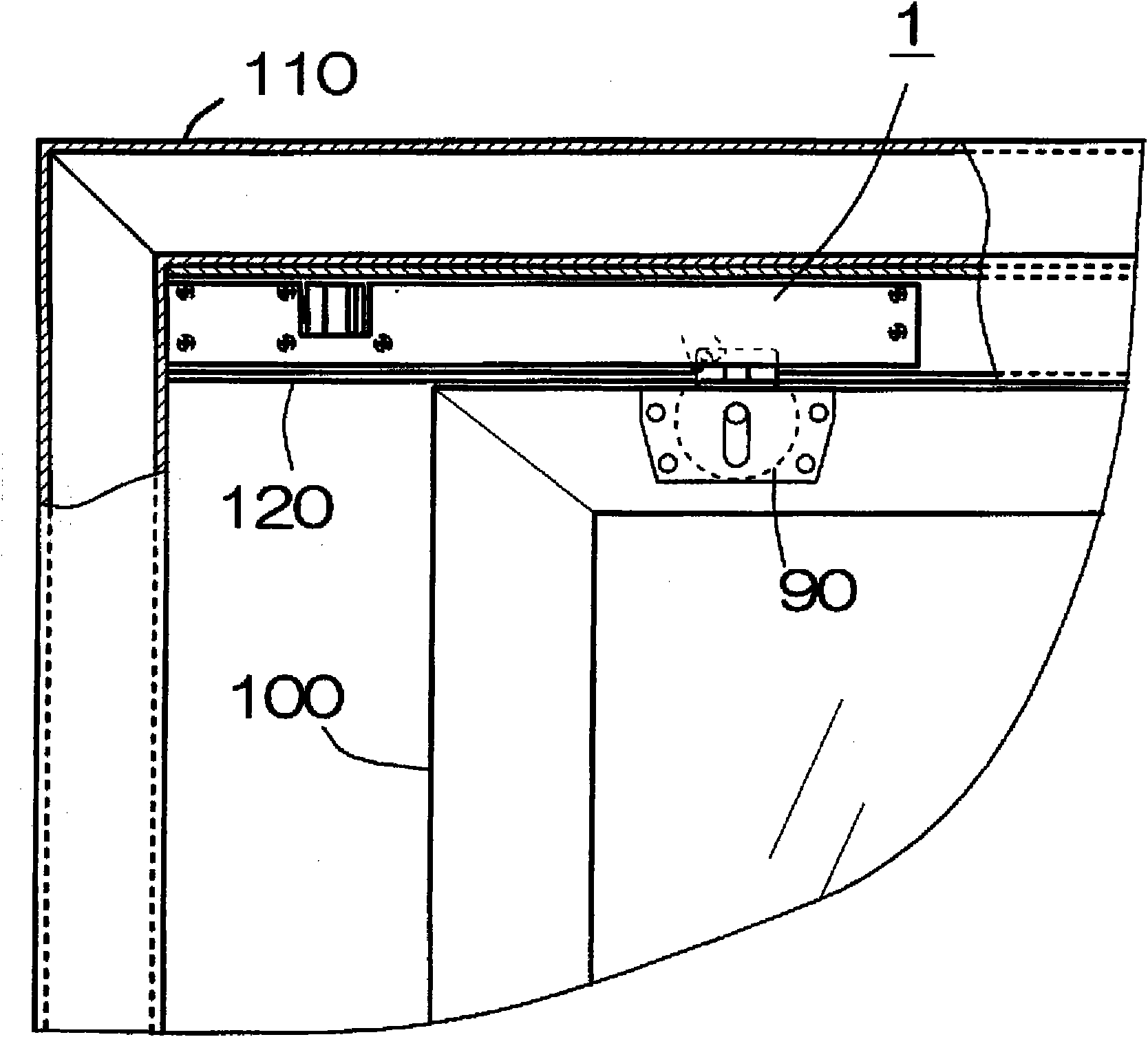
[0053] The buffer device provided by the first embodiment of the present invention will be described with reference to the drawings. figure 1 It is a front view of the upper part of a sliding door showing an example of installation of the shock absorber. In this figure, the frame material for the sliding door and a part of the upper rail are shown in cross section. The buffer device 1 is screwed and installed in the upper rail 120 of the sliding door frame material 110 mounted on the sliding door 100 . Buffer device 1, clamps the guide member 90 assembled on the upper end of sliding door 100 at the position about to completely close sliding door 100, prevents the closing inertia of sliding door 100 and prevents the collision sound when sliding door 100 is closed, prevents The rebound of the sliding door 100 caused by the collision. This cushioning device 1 forms a pair with a guide member 90 mounted on the upper end portion of the sliding door 100, and performs a cushioning f...

no. 2 Embodiment

[0077] Next, the drawing-in device for a sliding door provided by the second embodiment of the present invention will be described with reference to the accompanying drawings. Figure 15 is an exploded perspective view of the pull-in device, Figure 16 (a) is the front view of the pull-in device, Figure 16 (b) is the internal structure diagram of the pull-in device after removing half of the front shell. The pull-in device 200 further includes a coil spring (urging member) 29 for urging the slider 30 forward in addition to the configuration of the buffer device of the first embodiment. exist Figure 15 and Figure 16 In (a) and (b), the same reference numerals are assigned to the same parts as those of the shock absorber of the first embodiment.

[0078] The coil spring 29 is nested on the screw shaft 2 , its front end abuts on the rear end surface of the slider body 31 , and its rear end abuts on the rear end edge of the screw shaft arrangement part 9 in the fixing frame...

no. 3 Embodiment

[0081] Next, the pulling-in device provided by the third embodiment of the present invention will be described with reference to the accompanying drawings. Figure 17 is an exploded perspective view of the pull-in device 300, Figure 18 (a) is the front view of the pull-in device, Figure 18 (b) is the internal structure diagram of the pull-in device after removing the front half of the shell. The pull-in device 300 removes the rotary oil damper 18 and the damper spring 40 from the structure of the pull-in device provided in the second embodiment, and includes a slip clutch type rotary damper 15A instead of the thrust damper 15 .

[0082] In this pull-in device 300, after the forward movement of the screw shaft 2 is blocked as the slider 30 moves forward, the rotation of the screw shaft 2 is suppressed by the slip clutch type rotation damper 15A. Although the sliding clutch type rotary damper 15A has the same structure as the thrust damper in the first embodiment, it is diff...


PUM


Abstract

A shock absorber (1) includes, as main components, a spiral shaft (2) holding an abutting member (16) and a slider (30), a holder (5), an oil resistance type rotary damper (18), a damper spring (40) for urging the oil resistance type rotary damper (18) rearward, the abutting member (16) attached to the front end (3) of the spiral shaft (2), and a receiving member (17) on which the abutting member (16) can be made to abut. A drawing device (200) makes the shock absorber (1) fit a coil spring (29) for urging the slider (30) in the drawing direction to the spiral shaft (2), and makes the slider (30) support a hook member (34) rotatably such that sustention and switching can be made between the drawing posture and the drawing release posture.

Description

technical field [0001] The present invention relates to a buffer mechanism that suppresses the opening and closing tendency of sliding doors, partition doors, leaf doors, furniture drawers, curtains, etc. into the device. Background technique [0002] Sliding doors, partition doors, leaf doors, furniture drawers, curtains, etc., have the following problems: they are supported for smooth opening and closing, and there is a bumping sound when closing them by hand; they have some bounce due to rebounding when bumping. to open; and must be operated by hand to fully close sliding doors, etc. [0003] Conventionally, it has been known to use a cushioning device such as a cylindrical damper or a cushioning spring, and a pull-in device in order to eliminate these problems. However, the price of the cylindrical damper is high. In addition, the cylindrical damper and the buffer spring have a reverse thrust in the opening direction when opening the sliding door in the closed position...

Claims


Application Information

Patent Timeline
Patent Type & Authority Applications(China)
IPC IPC(8): E05F1/16E05F3/14E05F5/02
CPCE05F1/16E05F3/14E05Y2201/254E05Y2201/21E05F5/003E05Y2800/24E05F5/027E05Y2201/266E05Y2201/412
Inventor 明石和邦
Owner KYOEI KANAMONO SEISAKUSHO
Why Eureka
Try Eureka