Capacitance measuring circuit for touch sensor

A touch sensor, capacitance measurement technology, applied in the direction of measuring electrical variables, measuring resistance/reactance/impedance, measuring devices, etc., can solve the problems of unable to obtain the response characteristics of pins, unable to obtain sufficient charging and discharging, and consuming a lot of time.

Inactive Publication Date: 2010-09-08
POINTCHIPS CO LTD
View PDF0 Cites 25 Cited by
  • Summary
  • Abstract
  • Description
  • Claims
  • Application Information

AI Technical Summary

Problems solved by technology

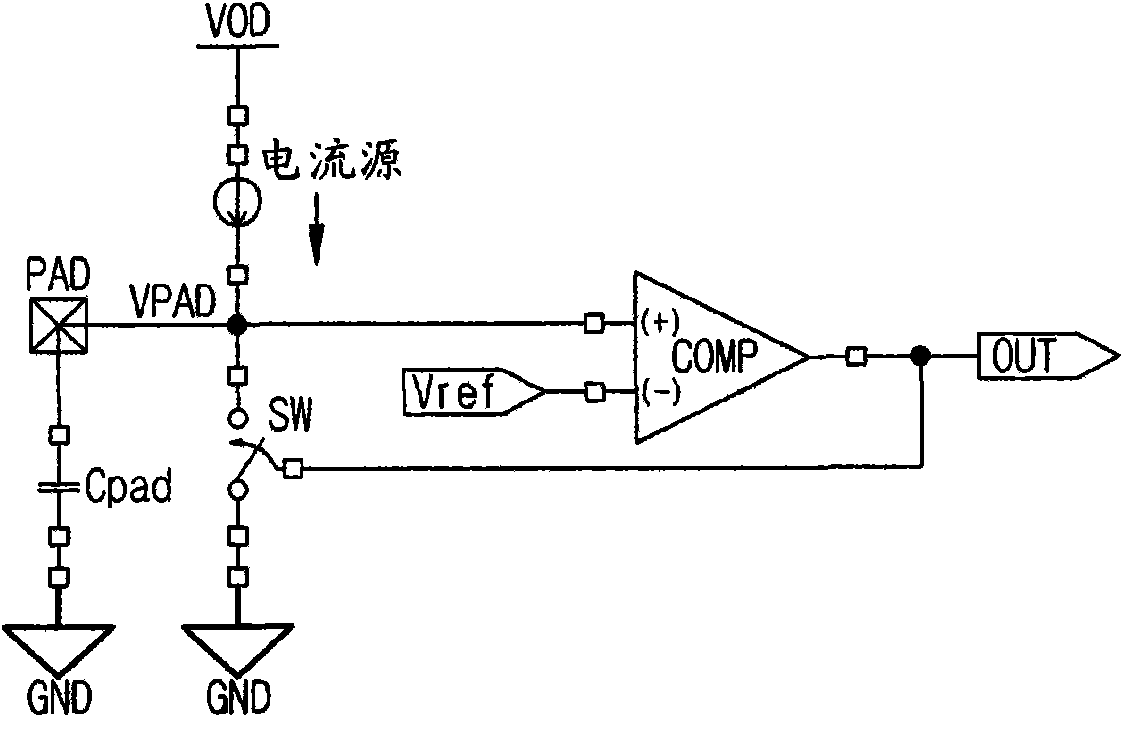
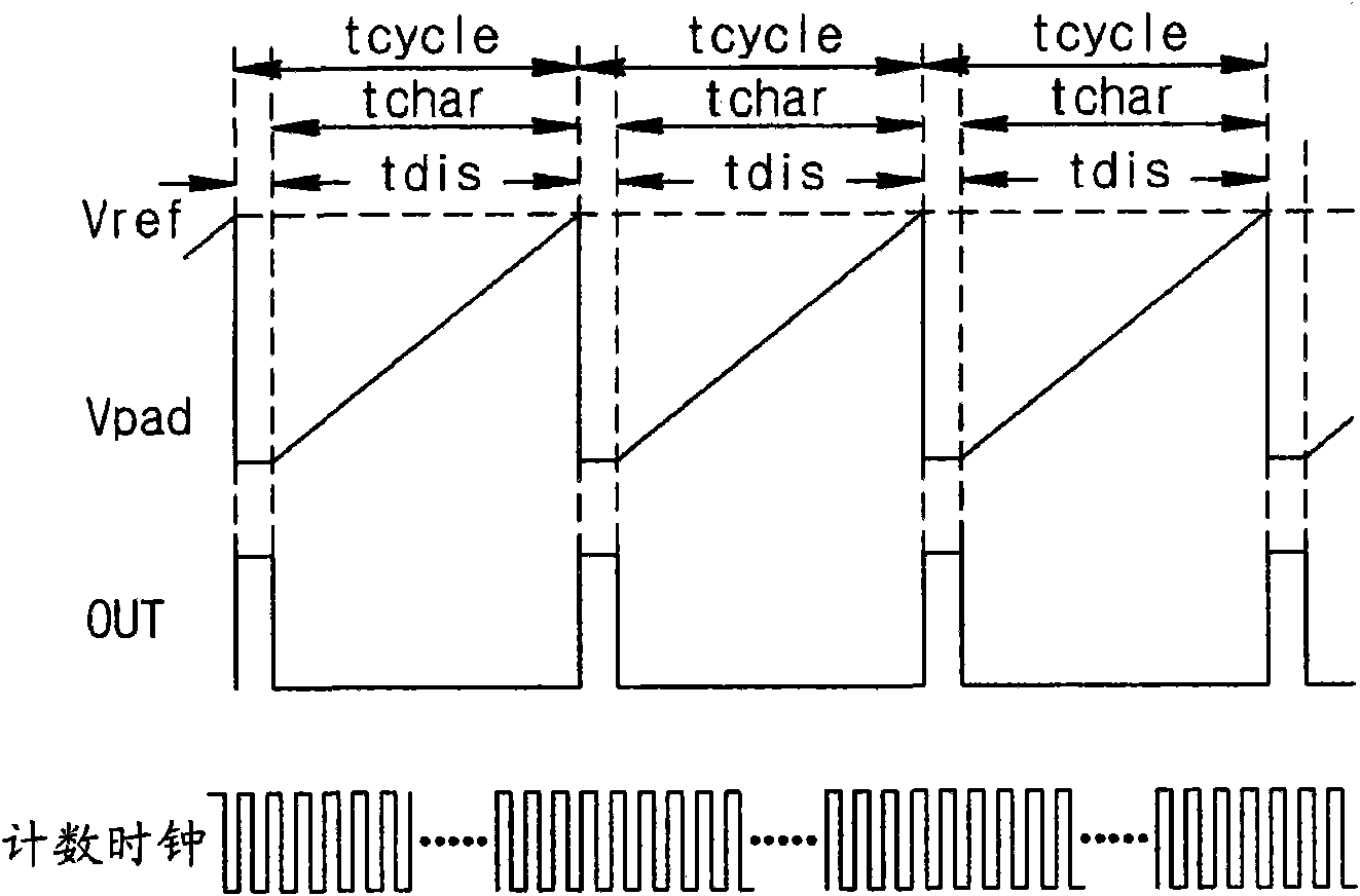
[0019] In addition, in order to deal with the situation that the timer value of sufficient charging and discharging cannot be obtained, the capacitance of the electrode is calculated by repeatedly executing the timer value measured by multiple tcycles, so that the time consumed by each electrode is more
Thus, in the case where a large number of electrodes PAD are provided and a touch sensor for sequentially measuring the capacitance of each electrode PAD is required, the response characteristic of each pin (pin) required by the user cannot be obtained.
Therefore, in the above case, there is a disadvantage in that it is necessary to use a plurality of touch sensor ICs

Method used


Image

  • Capacitance measuring circuit for touch sensor
  • Capacitance measuring circuit for touch sensor
  • Capacitance measuring circuit for touch sensor

Examples


Embodiment Construction

[0043] Below, an embodiment of a capacitance measurement circuit for a touch sensor according to the present invention will be described in detail with reference to the accompanying drawings.

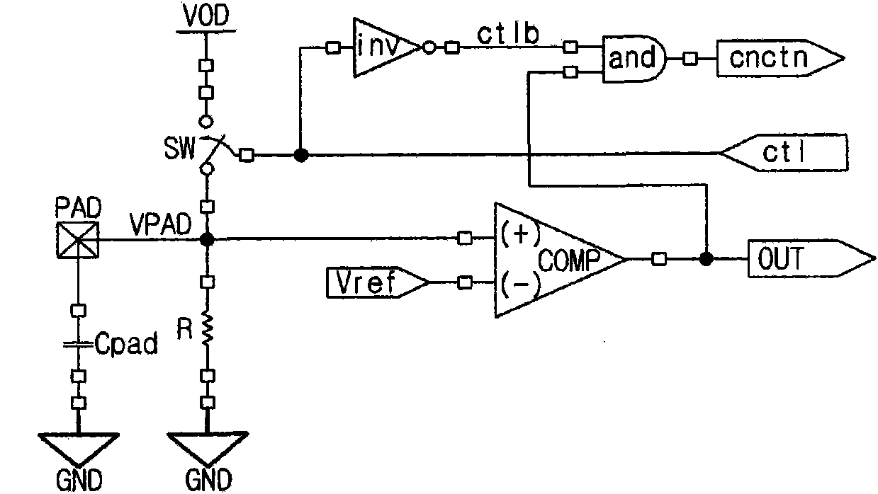
[0044] Figure 5 is a schematic diagram showing a capacitance measurement circuit for a touch sensor according to the present invention.

[0045] The capacitance measuring circuit for a touch sensor according to the present invention includes: a reference voltage generation unit 10, which is used to generate a first reference voltage and a second reference voltage; a multiplexing unit 60, which is used to generate from One electrode is selected in the electrode (PAD) 70; The comparator 20 is used for comparing the voltage generated by the above-mentioned reference voltage generating unit 10 with the voltage input from the above-mentioned electrode; Charge from the first reference voltage to the second reference voltage, or discharge the above-mentioned electrodes from the second refere...


PUM


Abstract

Disclosed herein is a capacitance measuring circuit for a touch sensor. The capacitance measuring circuit includes a reference voltage generation unit for generating a first reference voltage and a second reference voltage, a MUX unit for selecting one from among electrode voltages, a voltage comparator for comparing a voltage generated by the reference voltage generation unit with the electrode voltage, a charging / discharging circuit unit for performing charging of the input electrode voltage from the first reference voltage to the second reference voltage or performing discharging of the input electrode voltage from the second reference voltage to the first reference voltage, a timer unit for receiving an external control signal, measuring charging time and discharging time of the charging / discharging circuit unit, measuring entire charging time and entire discharging time, and outputting corresponding output signals, and a control unit for receiving an output signal of the voltage comparator and the external control signal, and controlling the charging / discharging circuit unit and the timer unit.

Description

technical field [0001] The present invention relates to a capacitance measuring circuit of a touch sensor, and more particularly, a capacitance measuring circuit of a touch sensor that performs time measurement by applying a predetermined constant current both at the time of charging and discharging, thereby measuring the capacitance of a corresponding electrode in a short time. Background technique [0002] The capacitance of the electrode PAD is determined by contact with a capacitor as an electrical element connected to the electrode PAD, a substance equivalent thereto, or a human body. In the case of contact with the human body, it can be seen that when a finger or a specific part of the human body is directly in contact with the electrode PAD, or when the electrode PAD is approached at an indeterminate distance without direct contact with the electrode PAD, there is a gap between the electrode PAD and the human body. A subtle capacitive component is generated. [0003]...

Claims


Application Information

Patent Timeline
Patent Type & Authority Applications(China)
IPC IPC(8): G01R27/26
CPCH03K17/955H03K2217/960705H03K2217/960715H03K17/962G01R27/26
Inventor 韩尚贤那道妍崔寅俊
Owner POINTCHIPS CO LTD
Why Eureka
Try Eureka