
Test point automatic positioning method and copper thickness automatic detection method and system

A technology of automatic positioning and testing points, applied in measurement devices, image data processing, instruments, etc., can solve the problems of cumbersome process and low efficiency, and achieve the effect of improving production efficiency, accurate and stable measurement

Pending Publication Date: 2020-08-25
GUANGDONG ZHENGYE TECH
View PDF10 Cites 3 Cited by
  • Summary
  • Abstract
  • Description
  • Claims
  • Application Information

AI Technical Summary

Problems solved by technology

At present, for the determination of the position coordinates of the test points, the traditional method still requires human intervention. For example, the operator uses measuring tools to measure the size of the positioning hole from the edge of the board. The process is very cumbersome and inefficient.
[0005] In view of this, how to provide an efficient and accurate test point positioning method to avoid the limitations of the prior art due to manual positioning is a technical issue to be solved urgently by those skilled in the art.

Method used


Image

  • Test point automatic positioning method and copper thickness automatic detection method and system
  • Test point automatic positioning method and copper thickness automatic detection method and system
  • Test point automatic positioning method and copper thickness automatic detection method and system

Examples


Embodiment 1

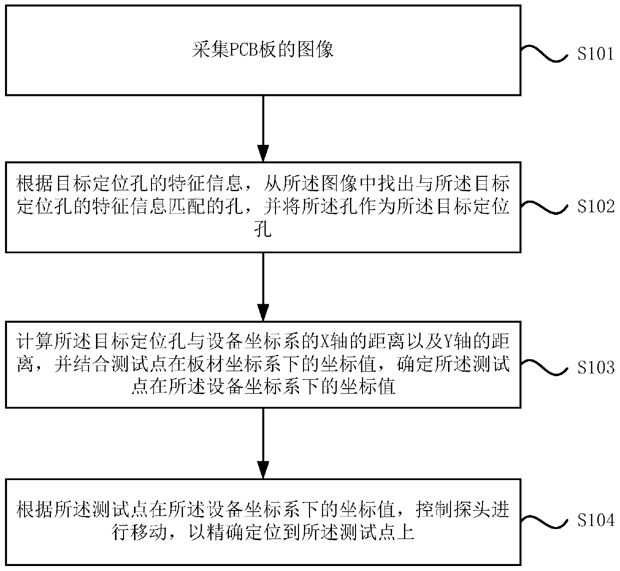
[0052] Please refer to figure 1 , figure 1 It is a schematic flow chart of a test point automatic positioning method provided in Embodiment 1 of the present invention. The method is suitable for the scene of automatic detection of PCB copper thickness. The method is executed by the test point automatic positioning system. The system can be controlled by software and / or Hardware implementation, integrated inside the automation equipment.

[0053] The method specifically includes the following steps:

[0054] S101. Collect images of the PCB board.

[0055] It should be noted that the image of the PCB board is collected by a CCD camera installed above the detection platform.

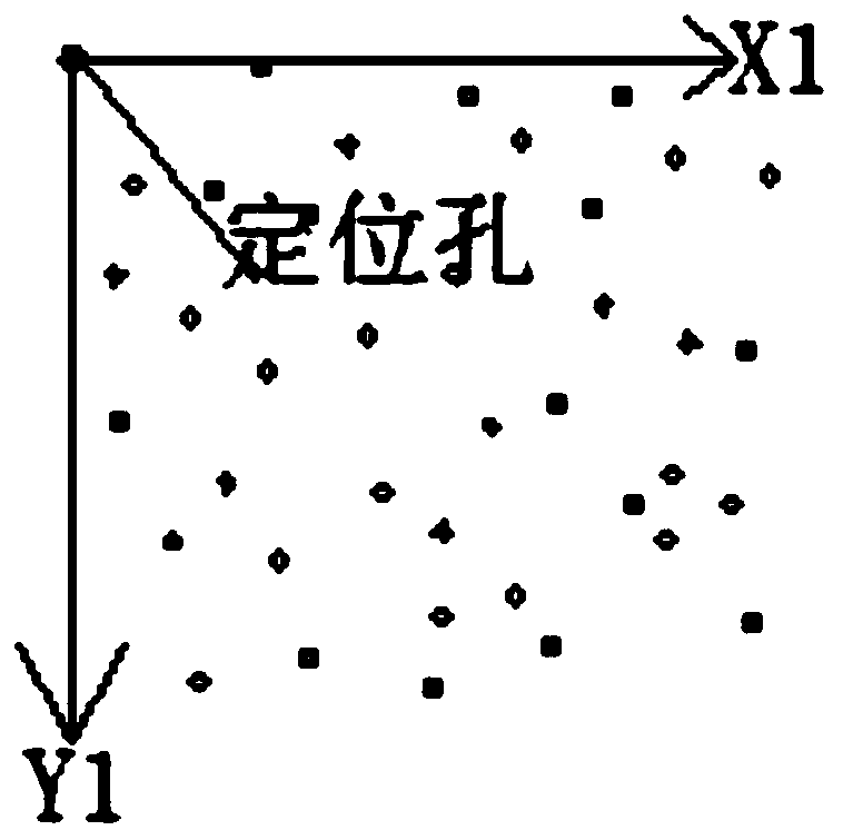
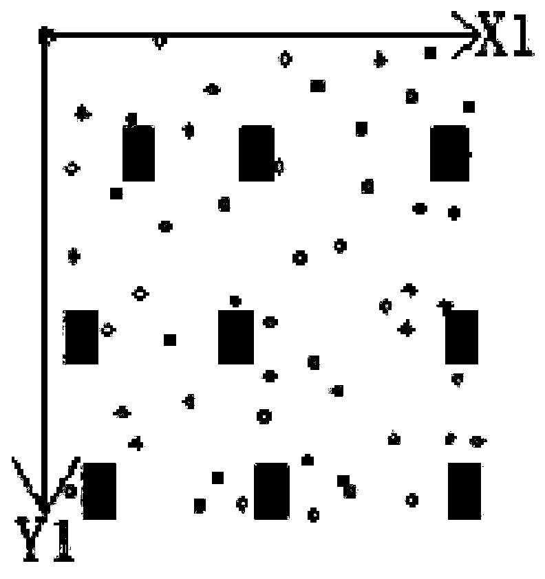
[0056] S102. According to the characteristic information of the target positioning hole, find a hole matching the characteristic information of the target positioning hole from the image, and use the hole as the target positioning hole.

[0057] It should be noted that the feature information may includ...

Embodiment 2

[0074] Please refer to Image 6 , an embodiment of the present invention provides a method for automatic detection of copper thickness, the method comprising:

[0075] S201. Position the probe on the test point of the PCB board.

[0076] Specifically, in this step, the positioning of the probe on the test point of the PCB is realized based on the automatic positioning method of the test point provided by the present invention. If the coordinate value of each test point in the device coordinate system is obtained, then it is only necessary to control the probe to move according to the coordinate value corresponding to each test point.

[0077] S202. Using the probe to measure the copper thickness data at the location of the test point.

[0078] An automatic copper thickness detection method provided by an embodiment of the present invention can determine the coordinate value of each test point on the PCB on the equipment coordinate system by converting the plate coordinate sy...

Embodiment 3

[0080] Please refer to Figure 7 , the embodiment of the present invention provides a test point automatic positioning system, the system includes:

[0081] Acquisition module 31, for collecting the image of PCB board;

[0082] The matching module 32 is configured to find a hole from the image that matches the feature information of the target positioning hole according to the feature information of the target positioning hole, and use the hole as the target positioning hole;

[0083] The calculation module 33 is used to calculate the distance between the target positioning hole and the X-axis and the Y-axis of the equipment coordinate system, and combine the coordinate values ​​of the test point in the plate coordinate system to determine the distance between the test point and the equipment coordinate system. The coordinate value under the system;

[0084] The control module is used to control the movement of the probe according to the coordinate value of the test point in...


PUM


Abstract

The invention discloses a test point automatic positioning method and a copper thickness automatic detection method and system. The method comprises the steps of collecting an image of a PCB; findingout a hole matched with the feature information of the target positioning hole from the image according to the feature information of the target positioning hole, and taking the hole as the target positioning hole; calculating a distance between the target positioning hole and an X axis and a distance between the target positioning hole and a Y axis of an equipment coordinate system, and determining a coordinate value of a test point in the equipment coordinate system in combination with a coordinate value of the test point in the plate coordinate system; According to the coordinate value ofthe test point under the equipment coordinate system, controlling a probe to move so as to be accurately positioned on the test point. According to the method, the coordinate value of each test pointon the PCB can be determined on the equipment coordinate system by converting the plate coordinate system and the equipment coordinate system, so that the probe can be automatically and accurately positioned on the test point, the accuracy and stability of copper thickness data measurement are ensured, and the production efficiency is improved.

Description

technical field [0001] The invention relates to the technical field of copper thickness automatic detection, in particular to an automatic positioning method for a test point, a copper thickness automatic detection method and a system. Background technique [0002] In the production process of the PCB board, the PCB board needs to be electroplated, and the copper layer is plated on both sides of the PCB board. In order to ensure that the transmission of current and signal meets the requirements of the PCB board, the copper thickness needs to be tested. [0003] At present, most of the detection of copper thickness in the PCB industry is still done manually by operators. Specifically, the operator manually moves the probe to a test point on the PCB, and then the probe performs copper thickness detection. This method consumes a high labor cost, and the detection accuracy is easily affected by the professionalism of the operator, and the production efficiency is extremely low....

Claims


Application Information

Patent Timeline
Patent Type & Authority Applications(China)
IPC IPC(8): G06T7/00G06T7/73G01B21/08
CPCG06T7/0004G06T7/73G01B21/08G06T2207/10004G06T2207/30141
Inventor 张也吴鹏辉胡孝楠郭浩延王兴李彬蔡林陈伯平
Owner GUANGDONG ZHENGYE TECH
Learn More