Steam heating soybean milk maker

A soymilk machine and steam technology, applied in the field of steam heating soymilk machine, can solve the problems of damaging the working performance of the motor, reducing the service life of the motor, increasing the working temperature of the motor, etc., so as to improve the service life, avoid damage, and avoid heat damage to the motor system damage effect

Inactive Publication Date: 2010-09-15
MIDEA GRP CO LTD
View PDF5 Cites 8 Cited by
  • Summary
  • Abstract
  • Description
  • Claims
  • Application Information

AI Technical Summary

Problems solved by technology

The motor and controller of this technology, that is, the machine head is set on the cup body. When the soy milk is heated, the steam generated by it rises and will direc...

Method used


Image

  • Steam heating soybean milk maker
  • Steam heating soybean milk maker
  • Steam heating soybean milk maker

Examples


Embodiment 1

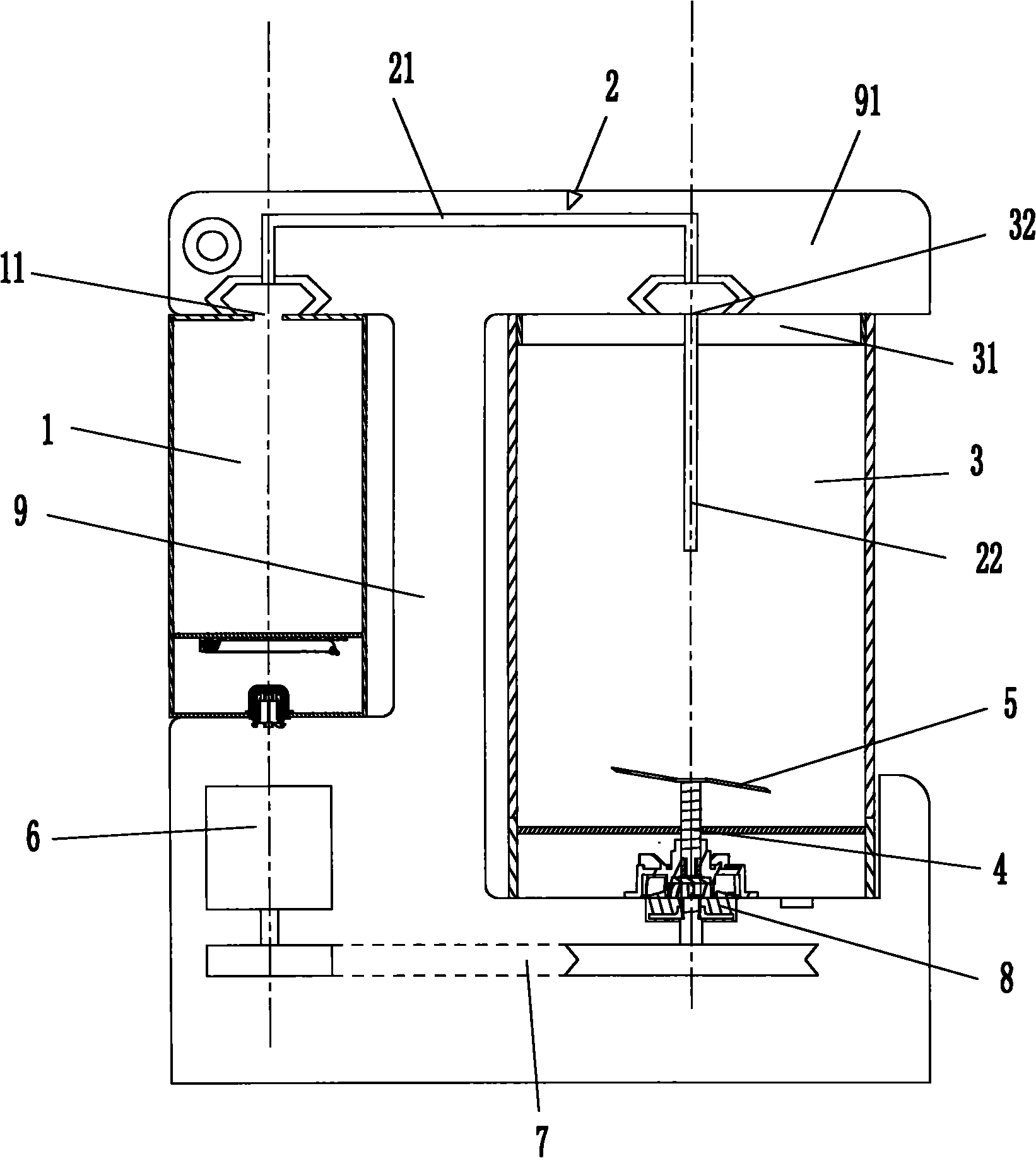
[0025] like figure 1 As shown, the present invention discloses a steam heating soymilk machine, comprising a steam generator 1, a steam pipeline 2, a cup body 3, a crushing device and a motor system, one end of the steam pipeline 2 is inserted into the cup body 3, and the other end is connected to the cup body 3 The steam outlet 11 of the steam generator 1 is connected, and the motor system is used to drive the pulverizing device, which is installed in the cup body 3, the pulverizing device is located at the bottom of the cup body 3, and the motor system is installed on the bottom of the cup body 3 sideways.

[0026] The steam generated by the steam generator 1 is transferred into the cup body 3 through the steam pipeline 2. As is well known, in order to achieve the effect of heating the slurry, the steam pipeline 2 needs to be inserted below the slurry liquid surface. In the present invention, when the slurry is heated, the slurry will generate steam and rise upwards, and th...

Embodiment 2

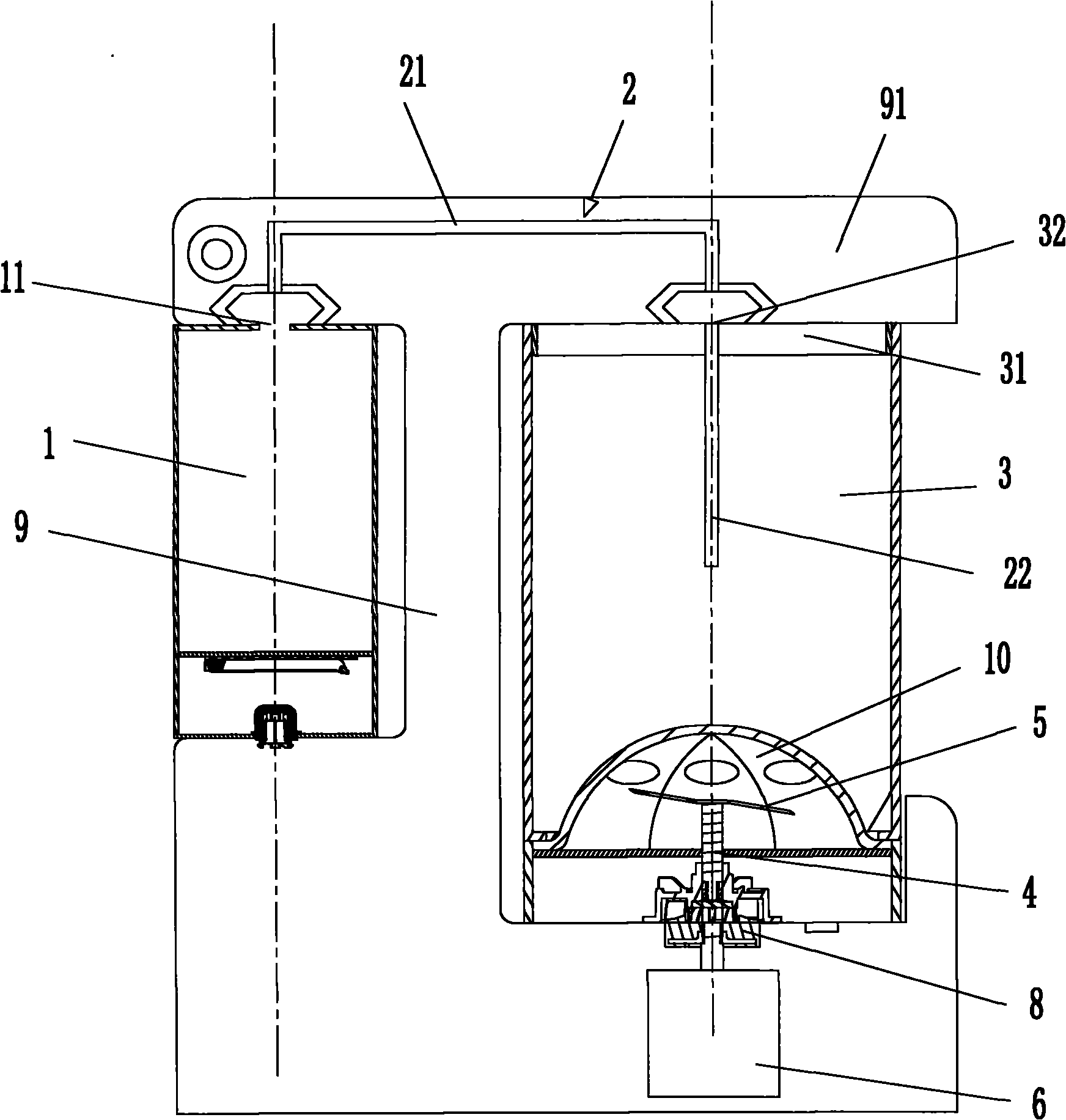
[0032] As a modified structure of Embodiment 1, this embodiment is similar to the structure of Embodiment 1, the difference is that, as image 3 As shown, the output shaft of the motor 6 is directly connected to the blade shaft 4 through a coupling 8 , and the motor 6 and its driving circuit are installed under the cup body 3 .

Embodiment 3

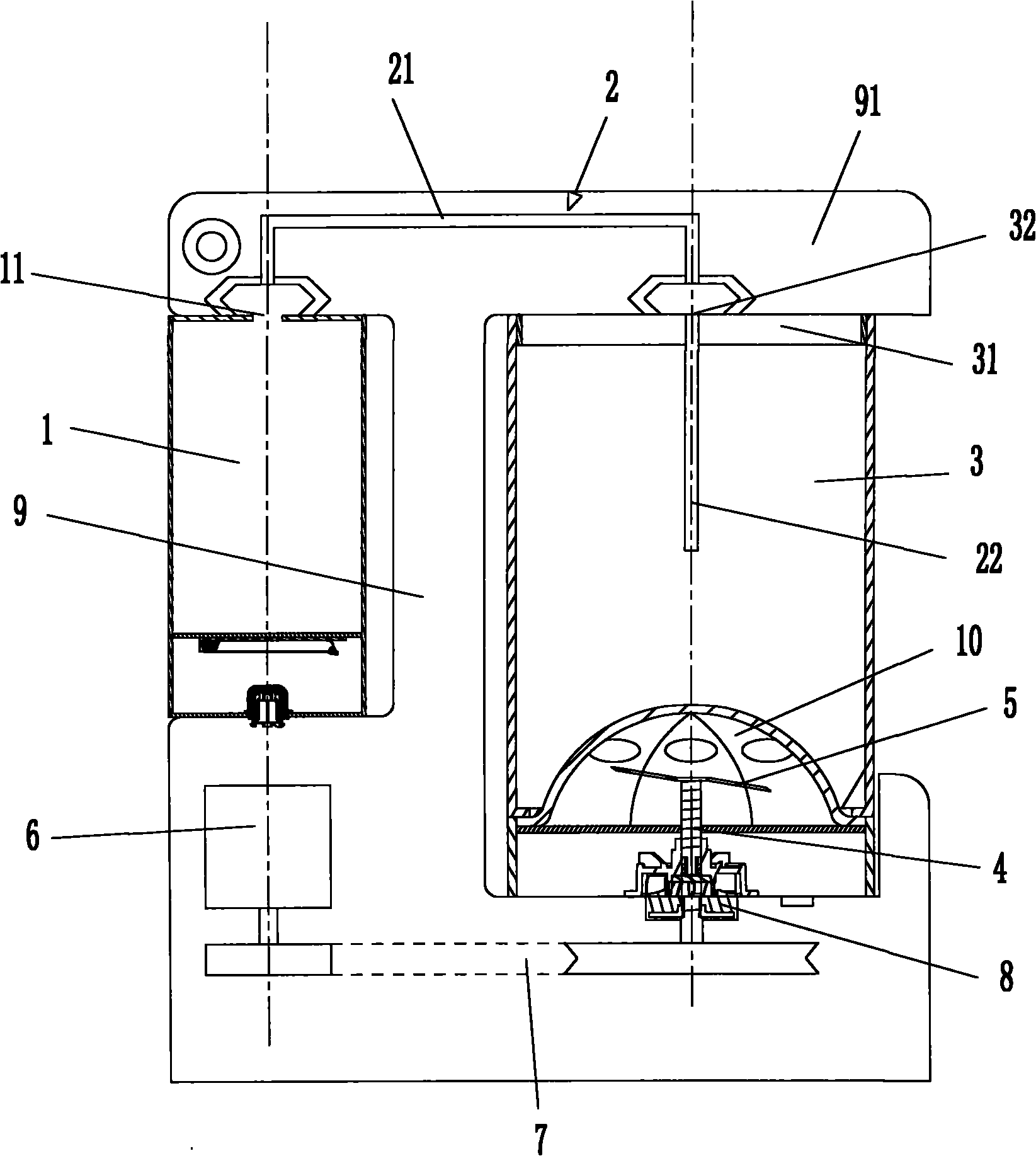
[0034] This embodiment is further limited on the basis of embodiment 1 or embodiment 2, specifically, as figure 2 As shown, the steam pipeline 2 includes a steam transmission section 21 and a steam output section 22, and the installation frame 9 is provided with an upper cover 91 movably connected with it, the steam transmission section 21 is arranged on the upper cover 91, and the steam output The section 22 is located in the cup body 3 , and the two ports of the steam transmission section 21 can be aligned with the through hole 32 and the steam outlet 11 respectively.

[0035] In this embodiment, when it is necessary to transfer the steam generated by the steam generator 1 into the cup body 3, it is only necessary to cover the upper cover 91; When the cover 91 is opened, due to the adoption of the lower structure of the motor system of the above-mentioned scheme at the same time, the use of the upper cover 91 is extremely convenient and light, avoiding the defects of heavy ...


PUM


Abstract

The invention belongs to the technical field of soybean milk makers and solves the problem that steam produced by heating soybean milk can damage the motor system. The invention particularly relates to a steam heating soybean milk maker which comprises a steam generator, a steam line, a cup body, a grinder and a motor system, wherein one end of the steam line is inserted into the cup body, and the other end is communicated with a steam outlet of the steam generator; the motor system is connected with the grinder; the grinder is installed at the bottom in the cup body; and the motor system is installed under or on the lateral side of the cup body. The invention can effectively prevent the motor system from being damaged by the steam generated by heating the soybean milk and prevent the motor system from being damaged by the heat generated by the steam line, thereby greatly prolonging the service life of the motor system.

Description

technical field [0001] The invention belongs to the technology of a soybean milk maker, in particular to a steam heating soybean milk maker. Background technique [0002] At present, soybean milk machine has been widely used, and it is often used in household soybean pulping to provide people with healthy soybean milk drink. [0003] Existing soymilk machines generally include the following parts, the cup body: used to hold water or soybean milk, and the "upper water level" line and the "lower water level" line are marked on the cup body to standardize the amount of water added to the cup body; : The machine head is the assembly of the soybean milk machine. Its shell is divided into an upper cover and a lower cover. The lower cover is used to install the main components, including the computer board, transformer and beating motor located in the lower cover. The lower part protruding from the lower cover has Blade, mesh cover, anti-overflow electrode, temperature sensor and ...

Claims


Application Information

Patent Timeline
IPC IPC(8): A47J31/44A23C11/10
Inventor 李前荣吴明川
Owner MIDEA GRP CO LTD
Why Eureka
Try Eureka