Mop bucket and supporting mop thereof

A mop bucket and mop technology, which is applied to the mop bucket and its matching mop field, can solve the problems of affecting the dehydration effect of the mop, the effective blocking part is small, the outer rod body is disengaged, etc., so as to achieve labor-saving, stable work, and reduced the effect of friction

Active Publication Date: 2010-09-15
赵一美
View PDF6 Cites 4 Cited by
  • Summary
  • Abstract
  • Description
  • Claims
  • Application Information

AI Technical Summary

Problems solved by technology

However, the effective blocking part between the hook and the fixed sleeve is small, so that when the outer rod is pulled up, the outer rod is easily disengaged from the inner rod
Furthermore, the above structure also increases the friction between the hook and the inner rod body, the fixed sleeve and the outer rod body, making the operation of pressing down and pulling up the outer rod body very laborious, increasing labor intensity and affecting the dehydration effect of the mop

Method used


Image

  • Mop bucket and supporting mop thereof
  • Mop bucket and supporting mop thereof
  • Mop bucket and supporting mop thereof

Examples


Embodiment 1

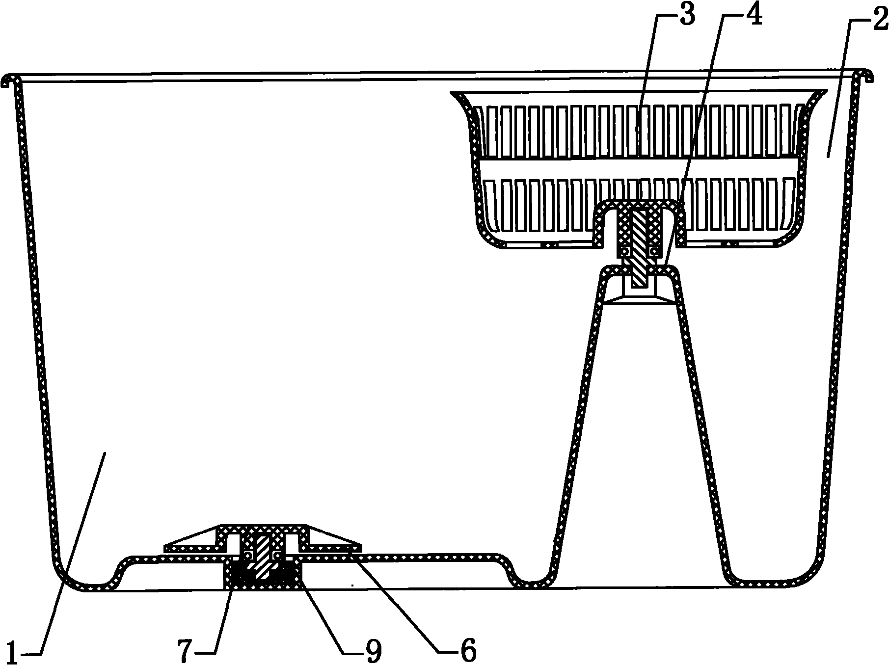
[0045] figure 1 , figure 2 , Figure 5 , Figure 6 , Figure 7 Embodiment 1 of the mop bucket of the present invention is given.

[0046] In this embodiment, a cleaning part 1 and a dehydration part 2 are arranged in the mop bucket, and a rotatable dehydration basket 3 is arranged in the dehydration part. The rotating mop head 5 is driven to rotate. A rotatable cleaning frame 6 is arranged in the cleaning part 1 , and the cleaning frame 6 is arranged at the bottom of the cleaning part 1 , and the cleaning frame 6 is driven to rotate by the rotating mop head 5 .

[0047] In this embodiment, a protrusion 7 is provided in the middle of the cleaning frame, and a positioning portion 8 matching the protrusion is provided in the middle of the mop head 5 . In this embodiment, the positioning portion 8 is an opening. The protrusion at the middle part of the cleaning rack cooperates with the positioning part at the middle part of the mop head to prevent the mop head from slippin...

Embodiment 2

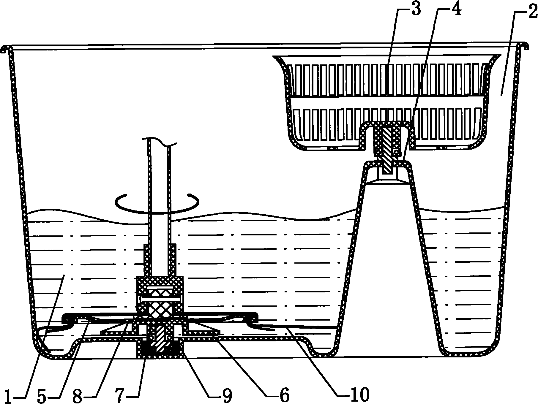
[0053] image 3 Embodiment 2 of the mop bucket of the present invention is given.

[0054] In this embodiment, the cleaning frame 6 interferes with the mop head during cleaning, and at least part of the wipes 10 on the mop head pass through the opening 11 on the cleaning frame. When part of the wipes on the mop head pass through the cleaning rack, the wipes passing through the cleaning rack can be rotated in the water under the drive of the mop head, which can fully contact with the water, and the dirt on the wipes can be wiped in the rotating Under the multiple effects of objects, rotating water and its own centrifugal force, it is easy to be cleaned, and its cleaning effect is very ideal. Simultaneously, the mop bucket can also be cleaned during the rotation process of the wiping objects passing through the cleaning frame. All the other are identical with mop bucket embodiment 1.

Embodiment 3

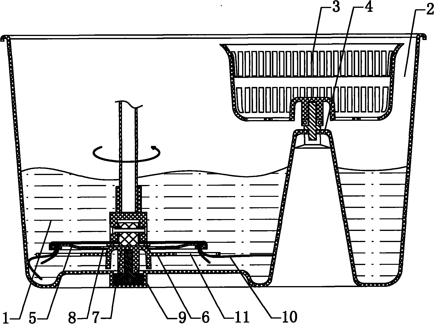
[0056] Figure 4 Embodiment 3 of the mop bucket of the present invention is given.

[0057] In this embodiment, the cleaning rack 6 is a cleaning basket, and when the mop head is being cleaned, all the wipes on the mop head are placed in the cleaning basket. The cleaning effect of this type of cleaning rack on the wipes is not as good as that of the aforementioned two structures, but its cleaning effect is much better than that of common cleaning methods. At the same time, the cleaning rack can reduce the noise during the cleaning process. All the other are identical with mop bucket embodiment 1.

[0058] Mop Example 1

[0059] Figure 5 , Figure 8 , Figure 9 , Figure 10 , Figure 11 Example 1 of the mop of the present invention is given.

[0060] In this embodiment, the mop matched with the mop bucket includes: the lower end of the mop rod is hinged with a mop head 5 with a wiper 10, and the mop rod at least includes an inner rod 12 and an outer rod 13, which can ...


PUM


Abstract

The invention relates to a mop bucket. A cleaning part and a dehydrating part are arranged in the mop bucket; a rotatable dehydrating basket is arranged in the dehydrating part; the dehydrating basket is arranged on an installing seat higher than the bucket bottom and is driven by a rotating mophead to rotate; a rotatable cleaning frame is arranged in the cleaning part; the cleaning frame is arranged at the lower part of the cleaning part and is driven by the rotating mophead to rotate; and because the rotatable cleaning frame is arranged in the cleaning part and the cleaning frame is driven by the rotating mophead to rotate to drive water in the mop bucket to rotate together, the mophead can be cleaned up. The cleaning frame of the invention can greatly improve cleaning effect.

Description

Technical field: [0001] The invention relates to a mop bucket and a mop matched with it. Background technique: [0002] At present, various mop bucket structures are numerous. Proposed a kind of " stepping-free dehydration barrel " as No. 200920160684.6 of Chinese patent. In this technical solution, the step-free dehydration bucket includes: a bucket body, a dehydration tank and a rotating part; wherein the top surface of the bucket body is an opening, and a mounting seat is raised from a bottom surface of the bucket body, And a shaft is fixed on the mounting base, the dehydration tank is sleeved on the support shaft; the rotating member is sleeved between the support shaft and the bottom of the dehydration tank, so that the dehydration tank is relatively The shaft is free to rotate. The step-free dehydration bucket can realize dehydration without stepping on it. But above-mentioned dehydration barrel can only adopt the mode of pulling up and down to clean mop head, and ...

Claims


Application Information

Patent Timeline
Patent Type & Authority Applications(China)
IPC IPC(8): A47L13/58A47L13/20
Inventor 赵一美
Owner 赵一美
Why Eureka
Try Eureka