
Automatic verifying system of multigroove electronic thermometer

An electronic thermometer, an automatic technology, applied in thermometers, thermometer testing/calibration, sensors, etc., can solve the problems of reducing the verification efficiency, fatigue, and missed detection of electronic thermometers, so as to improve the verification efficiency, avoid temperature control, and save temperature control time. Effect

Inactive Publication Date: 2010-09-15
CHINA JILIANG UNIV
View PDF5 Cites 19 Cited by
  • Summary
  • Abstract
  • Description
  • Claims
  • Application Information

AI Technical Summary

Problems solved by technology

The problem with the above verification method is that after working for a long time, the inspectors are prone to eye fatigue, which leads to misreading, false detection, missed detection and other problems.
The disadvantage of this device is: according to the national standard GB / T21416-2008 "Medical Electronic Thermometer", the electronic thermometer should be verified at six temperatures of 35°C, 36°C, 37°C, 38°C, 40°C and 41.5°C. Points are carried out separately, and the device disclosed in this patent uses the same constant temperature device to provide these temperature points
In this case, the time used to control the temperature field to make it stable often far exceeds the time necessary for the actual verification of the thermometer, which substantially reduces the efficiency of electronic thermometer verification

Method used


Image

  • Automatic verifying system of multigroove electronic thermometer
  • Automatic verifying system of multigroove electronic thermometer
  • Automatic verifying system of multigroove electronic thermometer

Examples


Embodiment approach 1

[0025] (1) Install 6 checked electronic thermometers on the 1# disc-shaped fixture, and install no thermometers on 2~6#.

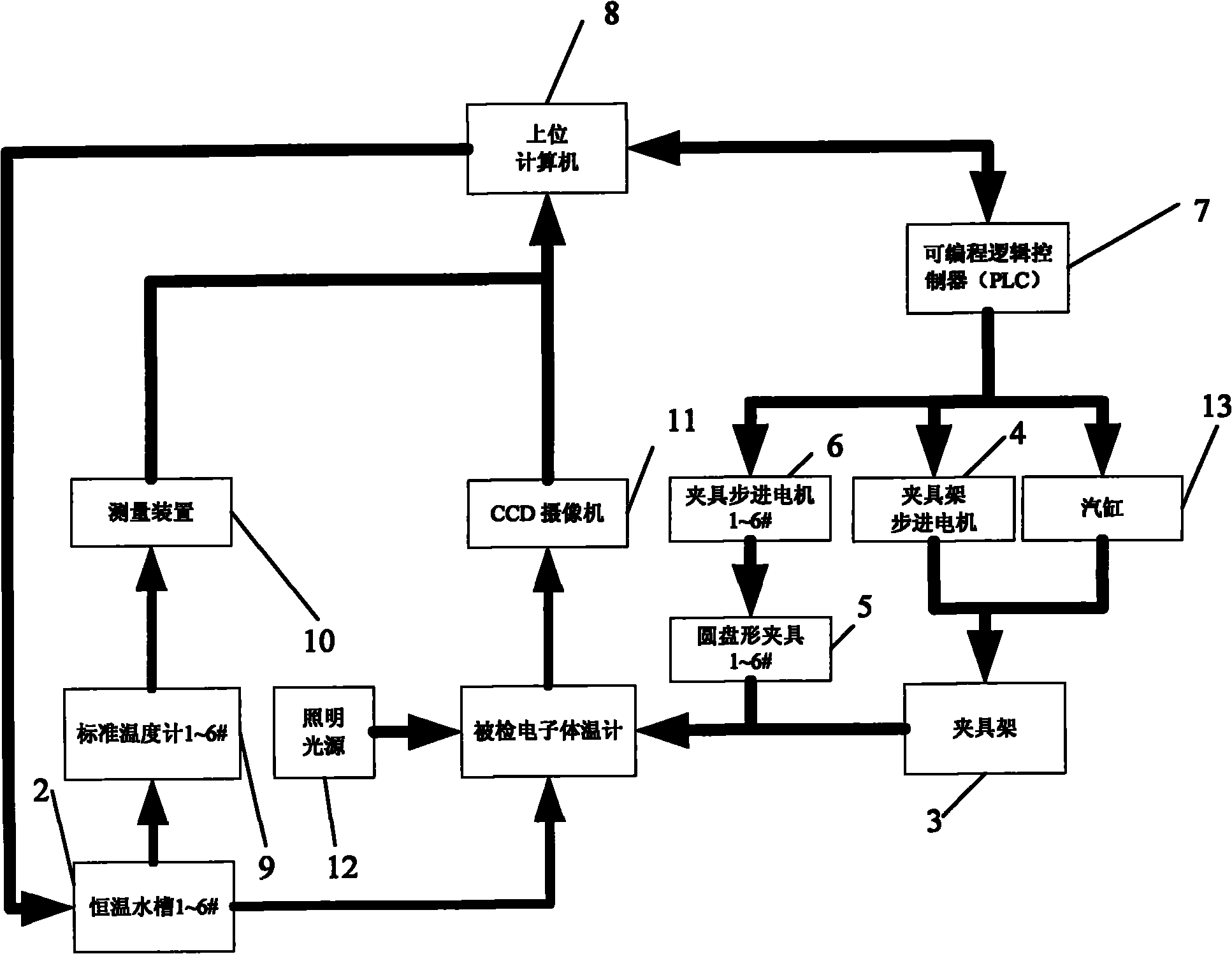
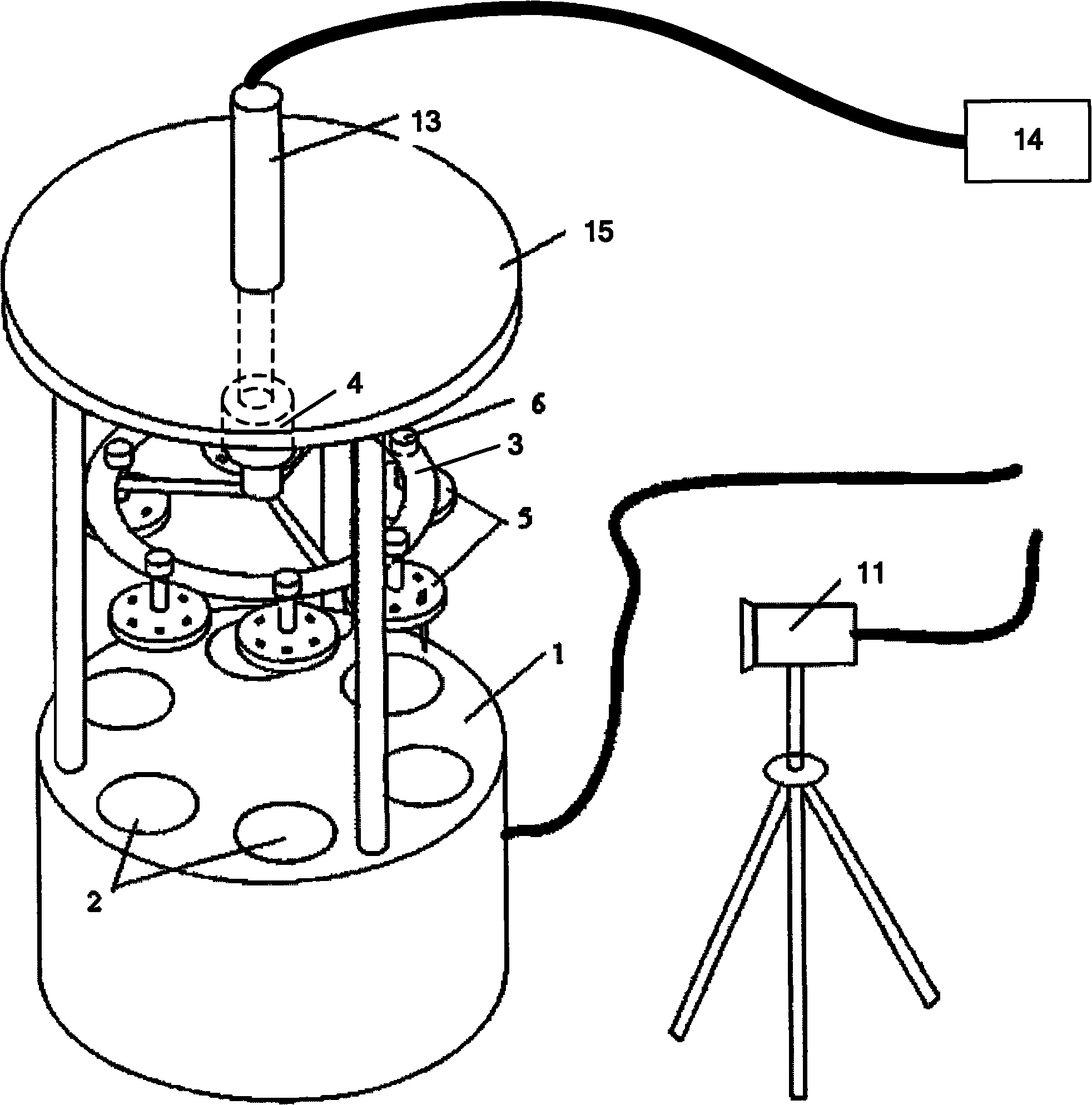
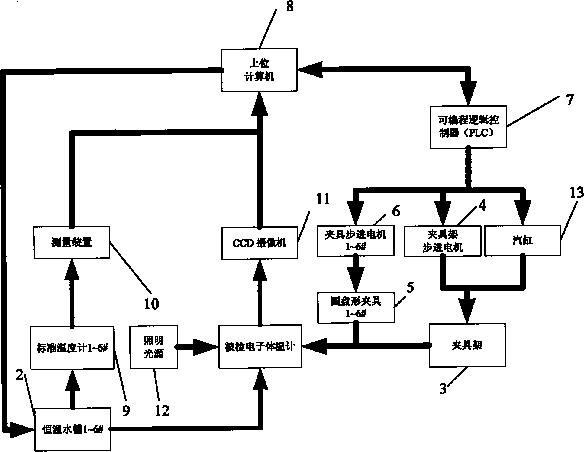
[0026] (2) The upper computer 8 sends instructions to the programmable logic controller 7 to control the fixture frame stepping motor 4 to rotate the fixture frame 3, so that the 1# disc-shaped fixture is aligned with the 1# constant temperature water tank, and then lower the fixture frame 5 and the disc The shape fixture frame 5 makes the sensor part of the checked electronic thermometer be inserted into the water. The disc-shaped fixture frame 5 is slidably matched with the water tank, which can cover the water tank, thereby reducing the influence of air flow on the constant temperature field.

[0027] (3) After reaching the time stipulated in the verification regulations or the manual of the tested thermometer, the host computer 8 sends an instruction to the programmable logic controller 7 to control the air pump 14 and the cylinder 13 to raise the chec...

Embodiment approach 2

[0034] (1) Install 6 checked electronic thermometers on the 1# disc-shaped fixture, and install no thermometers on 2~6#.

[0035] (2) The upper computer 8 sends instructions to the programmable logic controller 7 to control the fixture frame stepper motor 4 to rotate the fixture frame 3, so that the 1# disc-shaped fixture is aligned with the 1# constant temperature water tank, and then lowers the fixture frame 3 to make the tested The sensor of the electronic thermometer is inserted into the water.

[0036] (3) After reaching the time stipulated in the verification regulations or the manual of the tested thermometer, the host computer 8 sends an instruction to the programmable logic controller 7 to control the clamp frame stepper motor 4 to lift the checked electronic thermometer to a fixed position.

[0037] (4) Fine-tune the clamp frame by the clamp frame stepping motor 4 and rotate the 1# disc-shaped clamp by the clamp stepping motor 1#, so that the camera 11 can sequential...


PUM


Abstract

The invention discloses an automatic verifying system of an electronic thermometer. Six thermostatic water tanks are embedded into a verifying platform in an annular equal distance way; a clamp frame, clamp frame stepping motors and cylinders are coaxially installed on the verifying platform in sequence; the cylinder is installed on a support platform; six disk-shaped clamps are annularly installed under the clamp frame in equal distance and can rotate around respective centers by the drive of the clamp stepping motors; all the stepping motors and the cylinders can be connected with a programmable logic controller and then connected with a superior computer; standard thermometers are arranged in all the thermostatic water tanks and sequentially connected with a measuring device and the superior computer; a CCD (Charge Coupled Device) camera and an illuminating light source are installed outside the upper part of the verifying platform, and the CCD camera is connected with the superior computer. The invention prevents frequent control temperature change, saves temperature control time, and integrally improves the verifying efficiency of the electronic thermometer by mounting an independent thermostatic field for each verifying temperature point of the electronic thermometer.

Description

technical field [0001] The invention relates to a thermometer measuring system, in particular to an automatic verification system for a multi-slot electronic thermometer. Background technique [0002] The electronic thermometer is a body temperature measuring instrument widely used in health care and medical fields. In production enterprises, medical units, and measurement and verification departments, it is necessary to verify the electronic thermometer to determine whether it is qualified. The traditional verification method is manual verification, that is, the detector of the electronic thermometer to be tested and the standard thermometer are placed in the same constant temperature tank. After the display number is stable or the specified measurement time is reached, the measurement result is obtained through human eye readings, and then measured with the standard thermometer. The result is used as the agreed truth value to calculate the measurement error of the verifie...

Claims


Application Information

Patent Timeline
IPC IPC(8): A61B5/01G01K15/00
Inventor 陈乐富雅琼孙坚钟绍俊徐红伟黄艳岩
Owner CHINA JILIANG UNIV
Learn More